Advertisement
Quick Links
Advertisement

Summary of Contents for Himel ATSE2CM
- Page 1 ATSECM Controller Operation Manual Internal...
-
Page 2: Table Of Contents
Table of Contents 1. Product Introduction ......................4 2. Front panel touch button function ..................5 3. Front panel LED......................... 6 4. Working mode .......................... 7 5. Main menu ..........................7 6. Wiring diagram ........................15 7. Mechanical dimension and panel opening ..............18 8.Technical parameters ...................... - Page 3 Default with 3m controller cable Internal...
-
Page 4: Product Introduction
It is an ideal product of ATSE. ATSE2CM automatic transfer controller consists of microprocessor as core. It can precisely detect two- source 3-phase voltage and make precise recognition about abnormal voltage (over-voltage, under- voltage, missing phase, over-frequency, under-frequency) and output passive control digital. -
Page 5: Front Panel Touch Button Function
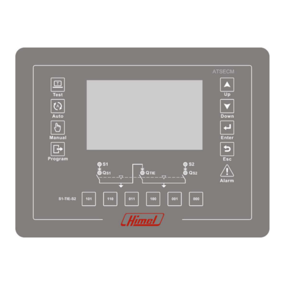
2.Front panel touch button function Icon Key name Function description In Manual mode, press this button to transfer breakers S1- 101 Key TIE-S2 to ON-OFF-ON(101 ) In Manual mode, press this button to transfer breakers S1- 110 Key TIE-S2 to ON-ON-OFF (110 ) In Manual mode, press this button to transfer breakers S1- 011 Key TIE-S2 to OFF-ON-ON (011 ) -
Page 6: Front Panel Led
3.Front panel LED ●Alarm LED (Red) –when fixed, indicates an alarm is active; ●S1 voltage status LED (Green) –S1 normal, fixed; S1 abnormal, blinking; ●S2 voltage status LED (Green) –S2 normal, fixed; S2 abnormal, blinking; ●Qs1 switch status LED (Green) –on, Qs1 close; off , Qs1 open; ●Qs2 switch status LED (Green) –on, Qs2 close;... -
Page 7: Working Mode
4.Working mode ● Programming mode: Parameter setting operation under this mode, long pressing “programming mode” key for 3s to enter, set password before visiting programming menu. ● Manual mode: Can control switch manually, long pressing “manual mode” button for 3s to enter, pressing 101 key、110 key、011 key、100 key、001 key、000 key switch the switch to the corresponding state. - Page 8 5.1、Public parameters Default Option Definition Adjustment Range 值 SYSTEM TIME Real time BACKLIGHT Active Active /1-30 Min BRIGHTNESS Standby / work 15/30 0-100/10-100 REGULATION PERMISSIONS Active Active /1-30 Min VALID TIME USER 1000 0000-9999 PASSWORD 5.2、System parameters Option Definition Default Adjustment Range NETWORK Network Type...
- Page 9 5.3、Switch setting: Option Definition Default Adjustment Range Pulse time of the opening and Signal hold time 0.5S 0.1-20.0S closing relay output When the output pulse is timed, Action timeout time If DI is not detected within the 0.5S 0.1-90.0S set time, the alarm is given The waiting time of the interlock Interlock time that before or after the closing of...
- Page 10 notes: INPUT1, INPUT2 and INPUT3 solidify for detecting Qs1, Qs2 and Qtie open or close state; INPUT4, INPUT5 and INPU6 solidify for detecting the fault state of Qs1, Qs2 and Qtie. Output function Output Menu Output code definition Inhibit Inhibit output function ATS ready The output signal is activated when switch and controller are OK SI available...
- Page 11 ● Power supply status icon, refer to pic1 page example Note Pic.1 Power supply status ● Data display icon, refer to pic2-pic8 page example Note Pic2 . Phase voltage(220V) Data display Pic3. Line voltage(380V) Data display Internal...
- Page 12 Data display Pic4. required conditions Data display synchronous transfer Programmable input, if Pic5. there is signal detected in Data display 01 input port, then the 01 will be selected. Programmable output, if Pic6. there is output action in 01 Data display output port, the 01 will be selected.
- Page 13 Pic8. Real time clock Data display ● Alarm status icon, refer to pic9 page example Note Alarm status, If there is Pic9. A01 alarm, A01 in the pic Alarm status will be selected ● Commissioning icon, refer to pic9 page example Note Pic10.
- Page 14 Pic11 Device Event record Event record Internal...
-
Page 15: Wiring Diagram
6. Wiring diagram 6.1 Terminal definition and description: Terminal Item Function description Note L1,N are AC power supply S1 AC 3-phase 4-wire voltage input terminal. L1,N are AC power supply S2 AC 3-phase 4-wire voltage input terminal. Module grounding Module ground terminal INPUT1 Break1 closure detection INPUT2... - Page 16 INPUT6 Break-TIE fault detection INPUT7 input port function defined by user INPUT8 RS485 communication interface RS485A RS485B RS485 grounding BATTERY+ Positive electrode of DC power supply BATTERY- Negative electrode of DC power supply OUT10 Relay COM auxiliary power output port Relay NO Relay NC OUT9...
- Page 17 6.2.Terminal diagram (ATSECM controller with air circuit breaker) Internal...
-
Page 18: Mechanical Dimension And Panel Opening
7. Mechanical dimension and panel opening 8.Technical parameters 1.AC supply: terminal 3,4 and 7,8 Rated voltage 400VAC(LL) Operating limit value 90-415VAC(LN) Frequency 45-65Hz Power consumption 2.DC supply:terminal 29,30 Rated battery voltage 24VDC Operating limit value 10-30VDC Max power consumption 3.Digital input:terminal 17—25 Input type negative Input current... - Page 19 4.RS485 serial interface:terminal 26,27,28 Interface Type isolation Baud rate 2400-38400bps 5、Output 31-33(OUT10) 、34-36(OUT9) 、37-39(OUT8)、40-42(OUT7) Contact Type single-pole double throw DC:10A、30V,AC:10A、250V Rated value 6、Output 43(OUT6)、45(OUT5)、46(OUT4) 、48(OUT3)、49(OUT2)、51(OUT1) Contact Type single-pole single throw Rated value DC:10A、30V,AC:10A、250V 7.Working environment condition Working temperature -25℃-70℃ -30℃-80℃ Storage temperature Relative humidity 20%-93%...
Need help?
Do you have a question about the ATSE2CM and is the answer not in the manual?
Questions and answers