
Related Manuals for Acute TravelLogic


Summary of Contents for Acute TravelLogic
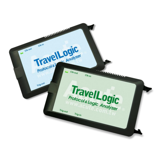
- Page 1 TravelLogic 2 in 1 Analyzer (Protocol + Logic) Manual Publish: 2018/06 Acute Technology Inc. Copyright 2018...
-
Page 2: Table Of Contents
Hide Data window ................23 Stack Oscilloscope................23 Cursor ........................24 Logic Analyzer ....................25 File ........................26 Capture ........................ 33 Quick Setting ..................33 Trigger Parameter Setting ..............34 Single Level Trigger ..............34 Acute Technology Inc. Copyright 2018... - Page 3 Stack Oscilloscope................42 Advanced Capture Setting ................... 47 Cursor ........................51 Waveform Area ....................54 Report Area ......................55 Bus decode Settings ..................... 56 Customized Report Settings ................56 Chapter 3 Technical support ................57 Acute Technology Inc. Copyright 2018...
-
Page 4: Chapter 1 Installation And Setting
Appearance and functions of the Master: Indicator LED Reference clock out Reference clock in Trigger out Trigger in USB 3.0 Type B slot: connected with computer. Pin assignment: Acute Technology Inc. Copyright 2018... -
Page 5: Software Installation
Please visit the official website of Acute Technology Inc., go to the Download page, and then select and download the TravelLogic 3000 series. After completion of installation, the “start icon” of TravelLogic 3000 series will appear on the desktop and the program set. You can select either one to start TravelLogic ( ). - Page 6 Acute Technology Inc. Copyright 2018...
-
Page 7: Specification Table
I² C, SPI, UART, USB PD3.0 BiSS-C, CAN2.0, DALI, HID over I² C, I² S, I³ C, LIN2.2, LPC, MDIO, Bus II Modbus, PMBus, Profibus, SMBus, SVI2, *SVID, USB1.1 eMMC4.5, Bus III eSPI, MIPI SPMI Acute Technology Inc. Copyright 2018... - Page 8 PMBus, Profibus, PWM, Protocol SMBus, *SVID, USB1.1, Monitor USB PD3.0 eSPI Zoom In / Out Language English / Simplified Chinese / Traditional Chinese Waveform Height Adjustable Zoom Report Software Window Features Quick Cursor-positioning Import Label(s) Quick Acute Technology Inc. Copyright 2018...
- Page 9 A 40-pin lead cable (32 / 2 / 2 / 4) Analog / GND) Grippers (Data / CLK / Analog / GND) *If you have any issues with SVID protocol features, please contact your Intel Field Representative. Acute Technology Inc. Copyright 2018...
-
Page 10: Chapter 2 Function List And Operation
Language: Display language. You can select English, Traditional Chinese, or Simplified Chinese System environment settings: Here you can set the working directory, the label height, whether to load the last setting, the waveform display mode and its color. Acute Technology Inc. Copyright 2018... -
Page 11: Capture
4. Options: You can set the capture and decoding parameters for Protocol. 5. Threshold: It can be set according to the voltage level of the signal. Style 2 for those protocols needs more setting Acute Technology Inc. Copyright 2018... - Page 12 2. Set the Sample Rate 3. Channel setting 4. Trigger on 5. Options: You can set the capture and decoding parameters for Protocol. 6. Threshold: It can be set according to the voltage level of the signal. Acute Technology Inc. Copyright 2018...
-
Page 13: Operating Mode And Memory Setting
Repetitive Times If it is not enabled, the device will be stopped after the stop condition matched. If it is enabled, the device will be stopped after the stop condition matched, then Acute Technology Inc. Copyright 2018... - Page 14 This function is set to OFF by default. Maximum Device Memory Limit Stop the capture when the device memory is filled to the set condition. Acute Technology Inc. Copyright 2018...
-
Page 15: Mode 2 Protocol Logger
Analyzer will be very great. Run data process after capture stopped Check this option to process the data after Logger capture stopped, or the software will only save the logger data without analyzing process. Acute Technology Inc. Copyright 2018... - Page 16 You can reload the .LOG file from Load file to re-analyze the data. Whether you check the results immediately or load them into the file, the file name will be converted from .LOG to .BFW. Acute Technology Inc. Copyright...
-
Page 17: Mode 3 Protocol Monitor
1. If the trigger is not set or you have set the trigger but want to retrieve the data before the memory is full, you must manually press “Stop” to send data back to the computer. Work options Maximum Device memory limit Acute Technology Inc. Copyright 2018... - Page 18 If the trigger condition is set, data will be filled according to the set Trigger Position. Data capture will continue until the trigger condition is met or “Stop” is pressed. Then, data capture will stop and the set memory will be filled. Acute Technology Inc. Copyright...
-
Page 19: Show Waveforms
2. Search the previous piece / the next piece of data. 3. Specifiy all fields or target fields for search. Specifiy fields for search can reduce the search range, thus speeding up the search. Acute Technology Inc. Copyright 2018... -
Page 20: To The End
2. Use the control buttons to move the current position, or input row number to jump to specified row. 3. Use the control buttons to add/remove selected row to Bookmark List. Saved as text file Contents of the report may be saved as .TXT or .CSV. Acute Technology Inc. Copyright 2018... -
Page 21: Detail Window
Many Protocols are equipped with a large number of numerical data, which cannot be appropriately displayed all together in the report window. Therefore, you can use the mouse to click the Data field on the report window to display the data in the detail window. Acute Technology Inc. Copyright... -
Page 22: Statistics Window
Data statistics are made according to the different characteristics of Protocols, so as to facilitate the understanding of the entire transmission situation, you may also click on the statistic trace to summarize all records of the selected trace into the statistic list window. Acute Technology Inc. Copyright... -
Page 23: Hide Data Window
"Convert to Logic Analyzer and Stack Oscilloscope" button to switch to the Logic Analyzer mode to enable this function. It should be noted that you must open Show Waveforms in the Protocol Analyzer mode and capture the data / waveform to switch. Acute Technology Inc. Copyright... -
Page 24: Cursor
Cursor This function includes the cursor setting and the waveform search function matching the cursor. Acute Technology Inc. Copyright 2018... -
Page 25: Logic Analyzer
6. Waveform Area: Mouse wheel can be used to zoom in/out the waveform scale; press Shift + Key to place cursors to calculate the time interval or frequency. Please refer to the cursor section below for the cursor usage. Acute Technology Inc. Copyright... -
Page 26: File
Save as: Save with a new file name and may set the storage range Save all: Save all files at once Saved as a PGV file: Convert captured waveform to PGV format for the Acute Digital Pattern Generator (PKPG, PG2000), which can be used to resend the digital signals. 1. Select PG Model The software will check the maximum working frequency and memory depth according to the selected PG model. - Page 27 If you select DSO Text File or LA Text File, you must go to the next step for advanced settings. Please be noted that the DSO Text File format will only be enabled when you have the BF6264B, LA3068B, LA3134B, TL3134B or TL3234B+ device connected. Acute Technology Inc. Copyright 2018...
- Page 28 3. LA Text File This format still requires further confirmation of separators, data start and time fields, etc. after the file is selected. The data start line default will be treated as the channel label name Acute Technology Inc. Copyright 2018...
- Page 29 When analyzing with the differential signal mode, it should be noted that the settings of the positive and negative channels must be the same, and the number of positive and negative channels must be matched to be able to analyze. Acute Technology Inc. Copyright...
- Page 30 The user can import waveforms from other logic analyzer into LA for analysis by arranging waveform data according to the following format. Batch Rpt. Save: Store the decode report to .CSV file from multiple captured waveform files. Batch Report Save Dialog↓ Acute Technology Inc. Copyright 2018...
- Page 31 1. Select the source waveform files, accepting file formats including Acute Logic Analyzer Waveform File .TLW or .LAW. 2. Select the file directory to save the converted report file, the saved file will be saved with source file name with different extension name.
- Page 32 Language: Display language. You can select English, Traditional Chinese, or Simplified Chinese System environment settings: Here you can set the working directory, the label height, whether to load the last setting, the waveform display mode and its color. Acute Technology Inc. Copyright 2018...
-
Page 33: Capture
Capture Quick Setting Required channels and related settings can be established quickly. If you specify to establish the bus decode, the sampling rate and threshold will be set according to the default conditions. Acute Technology Inc. Copyright 2018... -
Page 34: Trigger Parameter Setting
When adding a new state, you can press the button on the top to select the relationship between each state. The relationship between each state can be a continuous trigger (Next IF) or a non-continuous trigger (Then IF). Acute Technology Inc. Copyright... - Page 35 Acute Technology Inc. Copyright 2018...
-
Page 36: Width Trigger
This function is not supported when the sampling frequency is above 2 GHz (inclusive). Width Trigger The width trigger can set the trigger signal when the channel meets the trigger conditions and the length of the full pulse width. Acute Technology Inc. Copyright 2018... -
Page 37: Timeout Trigger
External Trigger The Trigger In input pulse signal of the device is taken as the trigger condition Acute Technology Inc. Copyright 2018... -
Page 38: Device Memory Usage
4. Trigger position: Percentage is used to set the trigger point in the memory. For example, if 50% is set, it indicates that up to 50% of the device memory will be retained to store the pre-trigger data. Acute Technology Inc. Copyright... -
Page 39: Threshold
0 or 1 at this critical point. This will cause trouble for viewing the waveform, as shown in Figure CH-01 below. Acute Technology Inc. Copyright... - Page 40 Threshold-High to be logic 1, and when the signal drops, the signal voltage to be measured must be lower than Threshold-Low to be recognized as logic 0. Those signals between the Threshold-High and Threshold-Low are falling in the non-transposed area. The last logical state is shown as below: Acute Technology Inc. Copyright 2018...
- Page 41 Acute Technology Inc. Copyright 2018...
-
Page 42: Stack Oscilloscope
Stack Oscilloscope Using TravelLogic and the Oscilloscope Stack functions, you need to install the special software provided by each oscilloscope brand. The software names are shown in the following table. DSO brand Software Acute DSO software Acute Please download the TEKVISA CONNECTIVITY SOFTWARE Tektronix from the Tektronix website. - Page 43 In Figure 1, the USB or Ethernet (TCP / IP) interface is connected to the computer, and then connect the BNC-MCX cable to the TravelLogic Trig-Out and the trigger input interface (Ext-Trig, Aux In or Trig-In) of the oscilloscope. MDO4000 series is fixed in the analog channel CH4.
- Page 44 In Figure 2, the BNC-MCX cable is connected to the TravelLogic Trig-In and the trigger output interface (Trig-Out) of the oscilloscope. After completing the above actions, press the "Stack Oscilloscope" button, as shown below: Select the DSO Select the brand that needs to be stacked on the oscilloscope. When there is no DSO hardware available for stacking, emulation is the mode used to read back the storage files of DSO stack.
- Page 45 Oscilloscope is set as the master, while the TravelLogic is set as the slave If the stack is composed of the oscilloscope as the master and TravelLogic as the slave, you must not only complete the above-mentioned basic settings but also set the external trigger signal.
- Page 46 Shift key, and then use the mouse’s left button to drag the DSO waveforms to the appropriate location to complete the stack delay correction. Stacking line: Standard MCX-MCX line for Acute DSO Optional BNC-MCX line (50cm or 100cm) for standalone DSOs Acute Technology Inc.
-
Page 47: Advanced Capture Setting
When the external clock stops, the signal capture will also stop, forming a synchronous operation between the two. Easy setting CK0 is used as the input clock when it is at the edge of Rising / Falling / Either. Acute Technology Inc. Copyright 2018... - Page 48 Take the following conditions as an example: CK0↑+Ck3=0 Sampling will take place immediately. CK0↑+Ck2=1 Sampling will take place immediately. CK2↓ Sampling will take place immediately. CK[3:0]=1001 or 0010 Sampling will take place immediately (without referring to the Edge conditions). Acute Technology Inc. Copyright 2018...
- Page 49 Channels that use the glitch filter function are marked with a red dot on the channel label for identification. Software Glitch filter settings Acute Technology Inc. Copyright...
- Page 50 Disabling this filter function will restore all waveform contents back to the original un-filtered waveform. Acute Technology Inc. Copyright...
-
Page 51: Cursor
Last Transition: Move to the last waveform transition Last Transition on Selected Label: Move to the last waveform transition of selected label Trigger Position: Move to the trigger position Cursor A-Z: Move to the Cursor position Acute Technology Inc. Copyright 2018... - Page 52 The starting point of the search is set to the current position of the selected cursor. Acute Technology Inc. Copyright 2018...
- Page 53 The value on the frequency / time display bar at the bottom right of the screen will change as the cursor moves. From left to right are the interval time, frequency calculation, the number of sampling statistics, respectively. Clicking the cursor name, you can switch the cursor. Acute Technology Inc. Copyright 2018...
-
Page 54: Waveform Area
This function can also be used in the waveform display area under the protocol Analyzer mode. Acute Technology Inc. Copyright... -
Page 55: Report Area
Negative Pulse Count Channel-to-Channel Rising Delay Channel-to-Channel Falling Delay Channel Rising to Channel Falling Delay Channel Falling to Channel Rising Delay Phase Delay 4. Report area storage Report contents can be saved as text files. Acute Technology Inc. Copyright 2018... -
Page 56: Bus Decode Settings
Reports, the preview window will show how many columns you have selected and combine them to create your customized report. Note: The Bus Decoders must be setup correctly in order to fetch the correct column names for the customized report. Acute Technology Inc. Copyright 2018... -
Page 57: Chapter 3 Technical Support
Demo mode during the execution of TravelLogic software, please try the following steps to solve the issue: (1) Install the latest version of the TravelLogic software, please go to the official website of Acute Technology Inc. - Download -... - Page 58 (4) Remove all probes and re-plug the USB3.0 Cable or restart the computer to check whether the driver appears. (5) After the above steps are taken but the problem is still there, please contact us. Acute Technology Inc. Copyright...
Need help?
Do you have a question about the TravelLogic and is the answer not in the manual?
Questions and answers