Table of Contents
Advertisement
Quick Links
Advertisement
Table of Contents

Subscribe to Our Youtube Channel
Summary of Contents for A-Plus Water DuraLine
-
Page 2: Table Of Contents
Description Application Installation Instructions Programming Flow Meter Control Board Data Recording Contact Information... -
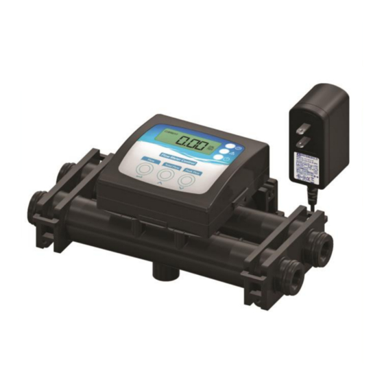
Page 3: Description
Meter Monitor Control • Displays real time flow rate in gallons per minute (GPM) • Set Volume/Set Time 12 V AC output • Total accumulated flow in gallons • 4-20 mA proportional flow rate output • Green LED light indicates power is on •... -
Page 4: Application
Application The meter control unit reads a standard Hall Effect water meter output to display flow. The meter control unit can also be used with industry standard auxiliary air pumps, chemical feeds, or other electro-mechanical products that require precision measures based on water usage. Installation The meter control is available as a companion to the complete line of water solution equipment. -
Page 5: Programming
Press and hold all 3 buttons on the display simultaneously for 3 seconds Total Flow button: Toggles the values up Peak Flow button: Toggles the values down Flow button: Press to advance to next screen Screen One: CLR MEMORY YES / NO ... - Page 6 Screen Four: SET THRESHOLD TOTAL 2 (factory set at 80) Set this option for the total amount of gallons required to deliver a service call alert to the customer Set threshold gallons (x1000) Recommended setting for 9x48 system is 80; 10x54 system is120 ...
-
Page 7: Flow Meter Control Board
Meter Control Board OPTO OUTPUT CONNECTION OUTPUT2 COMMON 4-20MA OUTPUT OUTPUT 1 CONNECTION 12 VAC-30MA POWER CONNECTION RED ALARM LED YELLOW WARNING LED GREEN POWER ON LED FLOW METER INPUT CONNECTION TERMINAL WARNING COLORS: BLACK, BUZZER WHITE, BLUE, AS SHOWN... -
Page 8: Data Recording
Job Description Date/Time Value (Before) Value (After) -
Page 9: Contact Information
Thank you again for choosing this Electronic Meter Assembly for your water treatment system. Please contact your service professional with questions. Place contact information here.
Need help?
Do you have a question about the DuraLine and is the answer not in the manual?
Questions and answers