Table of Contents
Advertisement
Quick Links
Installation and operation manual
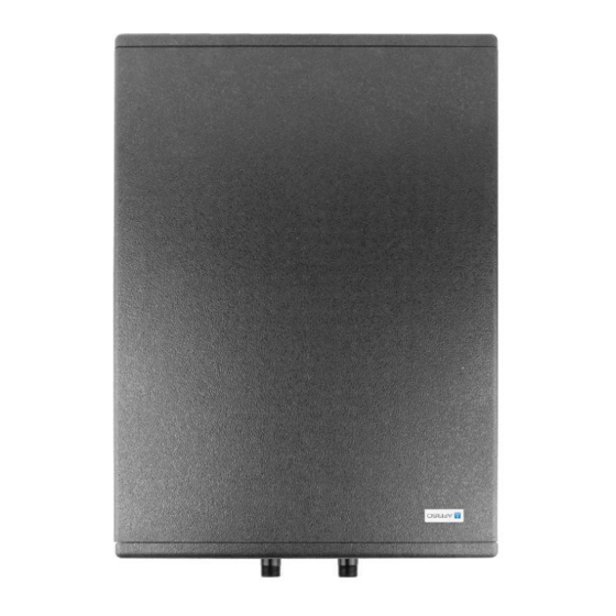
Buffer tank ABT 50
Art.- No 68 050 00
+
Read the manual before using the device
+
Pay attention to all information regatding safety
+
Keep the instruction manual
953.001.0160
AFRISO sp. z o.o.
Szałsza, ul. Kościelna 7
42-677 Czekanów
Phone
+48 32 330 33 55
Fax
+48 32 330 33 51
zok@afriso.pl
www.afriso.pl
Advertisement
Table of Contents

Subscribe to Our Youtube Channel
Summary of Contents for AFRISO ABT 50
- Page 1 +48 32 330 33 55 +48 32 330 33 51 zok@afriso.pl www.afriso.pl Installation and operation manual Buffer tank ABT 50 Art.- No 68 050 00 Read the manual before using the device Pay attention to all information regatding safety Keep the instruction manual...
-
Page 2: Table Of Contents
Installation and commissioning ................13 Selection and instalation of electric element ............15 10 Maintenance ......................17 11 Decommissioning, disposal ................... 17 12 Warranty ........................ 17 13 Copyright ....................... 17 14 Customer satisfction ....................17 15 Addresses ......................17 Buffer tank ABT 50... -
Page 3: Explanations To The Installation And Operation Manual
2 Information on safety 2.1 Intended use of the device The ABT 50 buffer tank is intended for use in a closed heating or cooling system in accordance with EN 12828. The ABT 50 buffer tank is designed for combining various heat/cooling sources with a heating/cooling system. -
Page 4: Quality Control
Instruction manual 2.2 Quality control Construction of buffer tank ABT 50 complies with the current state of the technical standards regarding safety. Each device is checked for safety before shipment. The product should only be used if it is in a qualified technical condition. -
Page 5: Product Description
Instruction manual 3 Product description The ABT 50 buffer tank is a heat or cold storage tank without a coil. It consists of a rectangular steel casing with welded connections and external, removable thermal insulation. The tank has a partial baffle... -
Page 6: Buffer Construction
Buffer front Buffer right and left side Connection G½” F Connection G½” F Heating element connection G1½” F Installation connections G1” Buffer top Buffer bottom Figure 1: Connection description of buffer tank ABT 50. Buffer tank ABT 50... -
Page 7: Dimensions
Instruction manual Dimensions Figure 2: Dimensions of buffer tank ABT 50 without insulation. Buffer tank ABT 50... - Page 8 Instruction manual Figure 3: Dimension of buffer tank ABT 50 with insulation. Buffer tank ABT 50...
-
Page 9: Buffer Operation
Instruction manual 3.3 Buffer operation The ABT 50 buffer tank is a storage tank for heat or cold that, once accumulated, can be used when the heat/cool source is switched off. This reduces the on/off frequency of the heat/cool source. -
Page 10: Examples Of Application Schemes
Instruction manual 5 Examples of application schemes Figure 4: Buffer tank ABT 50 used in installation with radiator and sur- face heating to connect two heat source: gas boiler and fireplace with water jacket. Buffer tank ABT 50... - Page 11 Instruction manual Figure 5: Buffer tank ABT 50 used in surface heating installation with monoblock type heat pump. Figure 6: Buffer tank ABT 50 used in surface heating instalation with split type heat pump. Buffer tank ABT 50...
-
Page 12: Technical Data
Buffer tank ABT 50 subject to the Pressure Directive 2014/68/EU and in accordance with art. 4.3 (sound engineering practice) are not CE marked. The ABT 50 complies with EU Regulation 812/2013 and EU Regula- tion 814/2013. Buffer tank ABT 50... -
Page 13: Installation And Commissioning
Instruction manual 8 Installation and commissioning The installation location of the ABT 50 buffer tank must provide pro- tection from the atmospheric factors. The buffer tank must not be in- stalled outdoors. It can be installed in any room protected from tem- peratures below 0°C. - Page 14 Instruction manual Depending on the orientation of the buffer, the supply and return connections from the system may be interchanged (see Fig. 8 for examples). Figure 8: Flows inside the buffer tank depending on connection manner. Buffer tank ABT 50...
-
Page 15: Selection And Instalation Of Electric Element
9 Selection and instalation of electric element Depending on the orientation of the ABT 50 buffer tank, the electric element can be screwed into a dedicated G1½" F connection or into one of the connections G1¼" F dedicated for a heat source. Depen- ding on the connection, the maximum installation length of the ele- ment will be different (Fig. - Page 16 Do not allow the element cover to come into contact with liquid. Disconnect the element from the mains before servicing. Do not make any changes to the device. Follow the guides which are included in element instruction manual. Buffer tank ABT 50...
-
Page 17: Maintenance
Dispose of the product in accordance with the local directives and guidlines. Buffer tank ABT 50 consist of materials that can be recycled 12 Warranty Product warranty in accordance with the general conditions of sale and delivery.

Need help?
Do you have a question about the ABT 50 and is the answer not in the manual?
Questions and answers