Table of Contents
Advertisement
Quick Links
Advertisement
Table of Contents

Summary of Contents for Paradigm Health & Wellness EXERPEUTIC
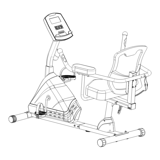
- Page 1 MyCloud Fitness App Recumbent Bike IMPORTANT: Read all instructions carefully before using this product. Retain this owner’s manual for future reference. The specifications of this product may vary from this photo, subject to change without notice. 4158.1-120219...
- Page 2 PLEASE DO NOT RETURN THIS PRODUCT TO THE STORE. STOP. Contact customer service if you have any questions regarding assembly or proper operation of the machine. Email us at: Service@paradigmhw.com Or call us at: 1-844-641-7921 Hours: 8:00 am to 5:00 pm (PST) Monday thru Friday...
-
Page 3: Table Of Contents
TABLE OF CONTENT SERVICE ------------------------------------------------------------------------ 2 LABEL PLACEMENT --------------------------------------------------------- 3 IMPORTANT SAFETY GUIDELINES------------------------------------- 4 OVERVIEW DRAWING ------------------------------------------------------ 6 PARTS LIST --------------------------------------------------------------------- 7 HARDWARE & TOOLS PACK ---------------------------------------------- 9 ASSEMBLY ---------------------------------------------------------------------- 10 CONSOLE ---------------------------------------------------------------------- 21 ADJUSTMENTS ---------------------------------------------------------------- 24 TRANSPORTING-------------------------------------------------------------- 25 TROUBLE SHOOTING & MAINTENANCE ----------------------------- 26 WARRANTY -------------------------------------------------------------------- 27 PARTS REQUEST FORM --------------------------------------------------- 28... -
Page 4: Service
SERVICE IMPORTANT: FOR NORTH AMERICA ONLY For damaged or defective product, questions, replacement parts or any other service support, please contact our customer service department by the below methods: For The Best Service, please Email: service@paradigmhw.com Response Time: 1-2 Business Days Emailing us with the information above will be the best method to receive a response during peak business hours Website:... -
Page 5: Label Placement
LABEL PLACEMENT... -
Page 6: Important Safety Guidelines
IMPORTANT SAFETY GUIDELINES Read all instructions before using the equipment. When using the equipment, basic precautions should always be followed. WARNING - To reduce the risk of injury to persons, read and under the following: Make sure your equipment is correctly assembled before you use it. Be sure all screws, nuts, and bolts are tightened prior to use. - Page 7 IMPORTANT SAFETY GUIDELINES Talk to your Doctor before using the equipment if you have any of the following conditions or ailments: Pregnancy Extreme obesity Middle ear infection Hiatus hernia or Ventral hernia Glaucoma, retinal detachment or conjunctivitis ...
-
Page 8: Overview Drawing
OVERVIEW DRAWING... -
Page 9: Parts List
PARTS LIST Description Description Phillips Self Tapping Screw Handrail End Cap Ø32x1.5 ST4.8x20 Hex Bolt M6x70 Right Decorate Cover Ø60 Flat Washer Ø6xØ12x1.0 Left Decorate Cover Ø60 Left Handrail Ø32x1.5x1085 Screw ST4.8x25 Backrest 465x465x135 Rear Stabilizer End Cap Ø60 Hand Pulse Sensor with Wire Cap Nut M8 L=1150 mm Screw ST4.2x30... - Page 10 PARTS LIST Description Description Hexagon Nut 7/8” Screw ST4.2x25 Cover Cap Ø40xØ25x10 Left Cover 672x83x448 Magnetic Brake Cable L=280 Right Cover 672x79x448 Right Foot Pedal (YH-63X) Front Main Frame 80x40x2 Crank with Belt Pulley Ø240 Power Supply Cable L=300 mm Hex Nut 1/2”...
-
Page 11: Hardware & Tools Pack
HARDWARE & TOOLS PACK... -
Page 12: Assembly
ASSEMBLY Tool: Multi Hex Tool with Phillips Screwdriver S10, S13, S14, S15 1PC STEP 1 1a. Front Stabilizer Installation: Lift up the Front Main Frame (73), and align the Front Stabilizer (78) onto the front curve of the Front Main Frame (73). Insert two Bolts (37) into the Front Stabilizer (78), then on the threaded ends of the Bolts (37) attach two Big Curve Washers (36) and two Cap Nuts (35). - Page 13 ASSEMBLY Tool: Multi Hex Tool with Phillips Screwdriver S10, S13, S14, S15 1PC STEP 2 2a. Installing the Rear Stabilizer: Lift up the Rear Main Frame (26), and align the Rear Stabilizer (38) onto the rear curve of the Rear Main Frame (26). Insert two Bolts (37) into the Rear Stabilizer (38), then on the threaded ends of the Bolts (37) attach two Big Curve Washers (36) and two Cap Nuts (35).
- Page 14 ASSEMBLY Tool: 6mm Allen Wrench with Phillips Screwdriver 1 PC STEP 3 3a. Hardware Removal: Use the 6mm Allen Wrench with Phillips Screwdriver provided to remove the six Hex Bolts (39) and the six Flat Washers (40) from the Rear Main Frame (26). 3b.
- Page 15 ASSEMBLY Tool: 6mm Allen Wrench with Phillips Screwdriver STEP 4 4.1 Hardware Removal: Use the Multi Hex Tool with Phillips Screwdriver to remove the four Hex Bolts (24) from the Back and Seat Support Bracket (17). 4.2 Installing the Right/Left Handrail Support Tubes: Align the holes of the Right Handrail Support Tube (21) and the Back and Seat Support Bracket (17).
- Page 16 ASSEMBLY Tool: 6mm Allen Wrench with Phillips Screwdriver STEP 5 5.1 Hardware Removal: Use the 6mm Allen Wrench with Phillips Screwdriver to remove the eight Hex Bolts (39) and the eight Flat Washers (40) from the Seat Sliding Tube (15). Retain the hardware for Back and Seat Support Bracket installation. 5.2. 5.2 Installing the Back/Seat Support Bracket : Attach the Back and Seat Support Bracket (17) onto the Seat Sliding Tube (15) using the eight Hex Bolts (39) and the eight Flat Washers (40) that were previously removed.
- Page 17 ASSEMBLY Tool: 6mm Allen Wrench with Phillips Screwdriver STEP 6 6.1 Hardware Removal: Use the 6mm Allen Wrench with Phillips Screwdriver provided to remove the four Flat Washers (40), four Hex Bolts (49), one Hex Bolt (39), and one Big Curve Washer (36) from the tube of the Front Main Frame (73).
- Page 18 ASSEMBLY Tool: Multi Hex Tool with Phillips Screwdriver S10, S13, S14, S15 1PC NOTE: The Cranks, Pedal Shafts, and Foot Pedals are marked “R” for Right and “L” for Left. STEP 7 7.1 Installing the Left and Right Foot Pedals: Insert the Left Foot Pedal (63) into the threaded hole in the left side of the Crank (62).
- Page 19 ASSEMBLY Tool: Multi Hex Tool with Phillips Screwdriver S10, S13, S14, S15 1PC 5mm Allen Wrench STEP 8 8.1 Installing the Backrest: Attach the Backrest (5) and Left Handrail (4) onto the Back and Seat Support Bracket (17), using four Hex Bolts (2) and four Flat Washers (3). Tighten the Hex Bolts (2) using the 5mm Allen Wrench provided.
- Page 20 ASSEMBLY Tool: 5mm Allen Wrench Fig. A STEP 9 Note: To prevent damaging the PULSE WIRE in the frame, make sure it is NOT pushed out when inserting the Hex Bolts (35). See Fig. A 9.1 Installing the Armrest: Align the holes of the Armrest (20), the Right Handrail (12), and the Right Hand Support Tube (21).
- Page 21 ASSEMBLY Tool: Multi Hex Tool with Phillips Screwdriver S10, S13, S14, S15 1PC STEP 10 10.1 Hardware Removal: Use the Multi Hex Tool with Phillips Screwdriver provided to remove the four Hex Bolts (45) from the back of the Console (43). Use the Multi Hex Tool with Phillips Screwdriver to remove the two Hex Bolts (46) from the right side of the Front Post (48) 10.2 Installing the Console: Connect the Extension Hand Pulse Sensor Wires III (44) and Extension Sensor Wire I (50) to the wires at the rear of the Console (43).
- Page 22 ASSEMBLY STEP 11 11.1 Installing Adapter: Plug one end of the Adapter (76) into the power jack of the Power Supply Cable (74) on the Left Cover (71). Before plugging in, make sure to carefully check the specifications on the Adapter (76). Plug the other end of the Adapter (76) into the electrical wall outlet.
-
Page 23: Console
CONSOLE Console Buttons: START/STOP BUTTON: 1. Starts and Pauses a workout. 2. Holding the button for 3 seconds will reset the console for a new workout. UP & DOWN BUTTON: 1. Press to Increase or decrease the value of the selected workout parameter when setting a workout goal: TIME, DISTANCE, CALORIES. - Page 24 CONSOLE Profile Program: The console has 24 Preset Program options to choose from to help challenge you and meet your fitness goals. See the diagram below. How to quick start a Program Profile: The first screen that appears when the console is turned on is program profile P1.
- Page 25 CONSOLE Recovery Program: The Recovery Program gives you feedback about the rate at which you heart recovers after a workout. The recovery rating is a value in which your personal fitness can be judged. Your recovery rating is calculated by evaluating how large the difference is between your peak heart rate at the end of a workout and your heart rate after 60 seconds of resting.
-
Page 26: Adjustments
ADJUSTMENT Adjusting the Rear Stabilizer End Cap and the Adjustable Leveler: To prevent shaking during a workout adjust the Rear Stabilizer End Caps (34) and the Adjustable Leveler (42) as needed to the level the Bike with the ground. Adjusting the Seat Forward or Back Turn the L Shape Knob (97) in a counter-clockwise direction until the seat can slide freely. -
Page 27: Transporting
TRANSPORTING Transporting the Bike Hold the Rear Stabilizer (38) and lift up the machine until the Transport Wheel (80) make contact with the floor. Push or pull the unit to the desired location, then gently lower the Rear Stabilizer (38) to the ground. STORAGE Store the recumbent bike in a clean and dry environment away from children and pets. -
Page 28: Trouble Shooting & Maintenance
TROUBLE SHOOTING & MAINTENANCE TROUBLE SHOOTING: PROBLEM: The recumbent bike wobbles when in use. SOLUTION: Turn the Rear Stabilizer End Caps on the Rear Stabilizer or the Adjustable Leveler on the bottom of the Rear Main Frame as needed to level the recumbent bike. See the Adjustments Section. -
Page 29: Warranty
WARRANTY MANUFACTURER’S LIMITED WARRANTY Paradigm Health & Wellness warrants to the original purchaser that this product is free from defects in material and workmanship when used for the purpose intended, under the conditions that it has been installed and operated in accordance with Paradigm’s Owner’s Manual. -
Page 30: Parts Request Form
PARTS REQUEST FORM Paradigm Health & Wellness, Inc. EMAIL THIS FORM WITH YOUR RECEIPT OF PURCHASE TO Service@paradigmhw.com NAME:_____________________________________________________________________________________ ADDRESS:__________________________________________________________________________________ CITY:________________________ STATE:_____________ ZIP:_______________________________________ TELEPHONE: (Day)______________________________________________________________________ (Night)_____________________________________________________________________ SERIAL#:___________________________________________________________________________________ MODEL#:___________________________________________________________________________________ PURCHASE DATE:___________________________________________________________________________ PLACE OF PURCHASE:_______________________________________________________________________ PART # DESCRIPTION “YOUR ORDER WILL BE PROCESSED WITHIN 3 BUSINESS DAYS” This form can also be faxed to #: 626-810-2166...
Need help?
Do you have a question about the EXERPEUTIC and is the answer not in the manual?
Questions and answers