Advertisement
Quick Links
Advertisement

Related Manuals for Hamplus MBD-12F

Summary of Contents for Hamplus MBD-12F
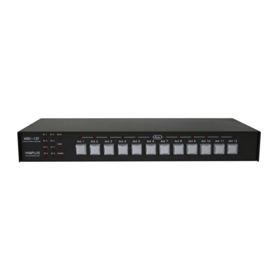
- Page 1 HAMPLUS MBD-12F Antenna Switch Controller Operation Manual V. 2.6 http://www.hamplus.com...
- Page 2 The MBD-12F records last antenna selected any time you change band or turn off the unit. When you turn on the MBD-12F, it read the frequency form the radio and auto selected the last antenna you used on the last band. The Rotator and GPI/O configuration are saved in the EEPROM memory too.
- Page 3 MBD-12F connected on the busy-net, so the antenna selected is in use, and cannot be selected by others unit. It does not allow another MBD-12F to select an antenna or rotator already in use. If you try to select an antenna in use the busy-net LED will flash for few seconds and the antenna won’t be selected when you release the push button.
- Page 4 It is permanent until you re-configure the receiving only antenna. To remove an antenna from EXCLUSIVE Reception mode a- First, select on the MBD-12F any antenna not in receiving mode, the SPLIT LED should be not be light.
- Page 5 8- Switching Rotors The MBD-12F also commands the RS-24, RS-44, RS-28 and RS-48 rotor switches. In this way a single rotor control can control up to 8 rotors. To configure the rotor switch, see item 12A 9- Communication with Icom, Yaesu, Kenwood, Elecraft K-3 and Flex Radio a.
- Page 6 11- Firmware update via USB To update the firmware, place the flash drive with the new Firmware in the USB port of the MBD-12F and reset the CPU by pressing the internal key or press and hold push buttons 10, then 11 and finally 12.
- Page 7 Ant1 button to the Ant8 button, which are flashing, press the Ant6 button. You are now in the antenna group configuration mode. From this moment on, the Master Antenna button will be flashing and all other antennas in this group will be illuminated. MBD-12F – Operation Manual Page 6...
- Page 8 Set the radio to 160m and choose the 160m antenna on the MBD-12F. Then set the radio to 80m and choose the antenna for 80m on the MBD-12F. Do this for all bands. After choosing the antennas enter the setup mode by pressing the push button 1.
- Page 9 All control pins are Active Hight + 12V TOPBEAM Waller Flag connector The HD-15 connector labeled TOPBEAM Waller Flag on the rear of the MBD-12F provides power (+12V) and controls for triggering the filters of the Waller Flag receiving antenna control box. The commands follow the Band data table or the Radio frequency.
- Page 10 BCD B from Radio BCD C from Radio BCD D from Radio DB-25 To ANTSW connector This connector connects the MBD-12F to the Antenna Switch and the Rotor Switch. It also offers I2C Commands for the Expansion Interfaces. Pins Function...
- Page 11 10- LAN ( for remote operation) 11- USB (for software update) 12- CI-V (for communication with Icom radios) 13- Buzy Net (P2 connector for communication between MBD-12F controllers) 14- Send In/Out (RCA connector type for SEND connection. It has internal relay) MBD-12F – Operation Manual...
- Page 12 Settings List of MBD-12F MBD-12F Settings All settings can be made directly from the keyboard in just two steps. First step to enter the setup mode. The second step is to choose the function you want to set. 1- First step...
- Page 13 If you turn off all the illuminated buttons the group will be undone and only the Master Antenna button will be flashing. c- To save and exit, press the button of the Master Antenna, the one that is flashing. ----------------------X--------------------- MBD-12F – Operation Manual Page 12...
- Page 14 MBD-12F – Operation Manual Page 13...
- Page 15 MBD-12F – Operation Manual Page 14...
- Page 16 MBD-12F – Operation Manual Page 15...
- Page 17 MBD-12F – Operation Manual Page 16...
- Page 18 MBD-12F – Operation Manual Page 17...
- Page 19 MBD-12F – Operation Manual Page 18...
- Page 20 MBD-12F – Operation Manual Page 19...
- Page 21 MBD-12F – Operation Manual Page 20...
- Page 22 MBD-12F – Operation Manual Page 21...
- Page 23 MBD-12F – Operation Manual Page 22...
- Page 24 MBD-12F – Operation Manual Page 23...
- Page 25 MBD-12F – Operation Manual Page 24...
- Page 26 MBD-12F – Operation Manual Page 25...
- Page 27 MBD-12F – Operation Manual Page 26...
- Page 28 MBD-12F – Operation Manual Page 27...
- Page 30 MBD-12F 31 DE MAIO DE 2022 4S INFORMATICA Rua Joe Collaco, 954 Florianopolis Brazil...
Need help?
Do you have a question about the MBD-12F and is the answer not in the manual?
Questions and answers