Table of Contents
Advertisement
Quick Links
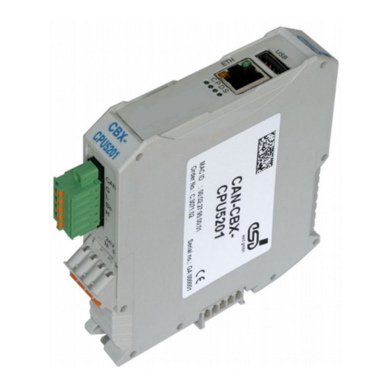
CAN-CBX-CPU5201
Powerful Realtime Controller
in a Smart Format
Hardware Manual
to Product C.3071.02,
C.3071.03,
C.3071.04,
C.3071.05,
C.3071.06
CAN-CBX-CPU5201
Hardware Manual • Doc. No.: C.3071.21 / Rev. 1.5
Page 1 of 53
esd electronic system design gmbh
Vahrenwalder Str. 207 • 30165 Hannover • Germany
http://www.esd.eu
Phone: +49 (0) 511 3 72 98-0 • Fax: +49 (0) 511 3 72 98-68
Advertisement
Table of Contents

Summary of Contents for ESD CAN-CBX-CPU5201
- Page 1 CAN-CBX-CPU5201 Hardware Manual • Doc. No.: C.3071.21 / Rev. 1.5 Page 1 of 53 esd electronic system design gmbh Vahrenwalder Str. 207 • 30165 Hannover • Germany http://www.esd.eu Phone: +49 (0) 511 3 72 98-0 • Fax: +49 (0) 511 3 72 98-68...
- Page 2 The information in this document has been carefully checked and is believed to be entirely reliable. esd makes no warranty of any kind with regard to the material in this document, and assumes no responsibility for any errors that may appear in this document. In particular descriptions and technical data specified in this document may not be constituted to be guaranteed product features in any legal sense.
- Page 3 4.6.1 Shield connected to FE Order information corrected Reference to chapter “Conductor Connection/Conductor Cross Sections“ inserted 2.3.1 Reference to chapter “Appendix CAN-CBX-CPU5201-PLC“ inserted Chapter “Starting-Up“ new Module CAN-CBX-CPU5201/DP QNX inserted 3.10 Software support revised, license information new 4.1, 4.2.1 Note inserted...
- Page 4 It is the responsibility of the device's user to take care that necessary safety precautions for the device's network interface are in place.
-
Page 5: Table Of Contents
1x RS-232 via COM1, 1x RS-485 via COM2 ............32 4.5.4 Connector Assignment....................33 Optional Profibus DP Interface.....................34 4.6.1 Connector Assignment....................35 Assignment of the Labelling to Name in Schematic Diagram ..........36 Conductor Connection/Conductor Cross Sections...............37 CAN-CBX-CPU5201 Hardware Manual • Doc. No.: C.3071.21 / Rev. 1.5 Page 5 of 53... - Page 6 ....................49 7.2.1 Configuration of the Network Settings.................49 7.2.2 Configuration of the IP-Address with CODESYS............50 7.2.3 Indication of the CAN-CBX-CPU5201-PLC LEDs............50 8. References..........................51 Declaration of Conformity......................52 Order Information........................53 Page 6 of 53 Hardware Manual • Doc. No.: C.3071.21 / Rev. 1.5...
- Page 7 0x, and binary numbers have a prefix of 0b. For example, 42 is represented as 0x2A in hexadecimal and 0b101010 in binary. Abbreviations Application Programming Interface Controller Area Network Central Processing Unit CAN in Automation Input/Output CAN-CBX-CPU5201 Hardware Manual • Doc. No.: C.3071.21 / Rev. 1.5 Page 7 of 53...
-
Page 8: Overview
Electrical Isolation Figure 1: Block circuit diagram The CAN-CBX-CPU5201 is a stand-alone module with a powerful 400 MHz PowerPC, 0.5 GB DDR2-SDRAM, 1GB NAND-Flash and RTC with battery backup on-board. The two CAN interfaces are designed according to ISO11898-2 high-speed layer and support bit rates up to 1 Mbit/s. -
Page 9: Hardware Installation
Hardware Installation 2. Hardware Installation 2.1 Connecting Diagram Fig. 2: Connecting diagram of CAN-CBX-CPU5201/DP Note: See also page 26 ff. for signal assignment of the CAN connectors. For information about conductor connection/conductor cross sections see page 37. CAN-CBX-CPU5201 Hardware Manual • Doc. No.: C.3071.21 / Rev. 1.5... -
Page 10: Coding Switch E.g. For Profibus Dp Slave Address
The operating system BSPs (Board Support Packages), which are currently available, support functions for reading the coding switch position. Please see the documentation of your BSP for further information. Page 10 of 53 Hardware Manual • Doc. No.: C.3071.21 / Rev. 1.5 CAN-CBX-CPU5201... -
Page 11: Led Display
Hardware Installation 2.3 LED Display Figure 4: Position of the LEDs 2.3.1 LED Indication For the indication of the LEDs C, P, D, S of the CAN-CBX-CPU5201-PLC see chapter: “Indication of the CAN-CBX-CPU5201-PLC LEDs” (page 50) Function Indication Description CAN Activity - Transmission of CAN data... -
Page 12: Assignment Of Led Labelling To Name In The Schematic Diagram
Table 2: Indication of the Ethernet LEDs 2.3.1.1 Assignment of LED Labelling to Name in the Schematic Diagram Labelling on the Name in Schematic Diagram* CAN-CBX-CPU5201 LED 1400A LED 1400B LED 1400C LED 1400D * The schematic diagram is not part of this manual. -
Page 13: Starting-Up
Mount the CAN-CBX-CPU5201 module and connect the interfaces (power supply voltage, CAN, etc.). Please note that the CAN bus has to be terminated at both ends! esd offers special T- connectors and termination connectors. Additionally the CAN_GND signal has to be connected to earth at exactly one point in the CAN network. -
Page 14: Installation And Wiring Of The Module
It is not intended as protective measure and does not protect against accidental contact. Note: EG-Conformity (see page 52) can only be guaranteed, if the earthing via the mounting rail is made as described. Page 14 of 53 Hardware Manual • Doc. No.: C.3071.21 / Rev. 1.5 CAN-CBX-CPU5201... -
Page 15: Installation Of The Module Using The Inrailbus Connector
Swivel the CAN-CBX module onto the mounting rail in pressing the module downwards according to the arrow as shown in figure 7. The housing is mechanically guided by the DIN rail bus connector. CAN-CBX-CPU5201 Hardware Manual • Doc. No.: C.3071.21 / Rev. 1.5 Page 15 of 53... - Page 16 CAN signals InRailBus ..24 V ..Power supply voltage Figure 9: Wiring diagram with CAN-CBX-CPU5201 as bus master Page 16 of 53 Hardware Manual • Doc. No.: C.3071.21 / Rev. 1.5 CAN-CBX-CPU5201...
-
Page 17: Connecting Power Supply And Can Signals Via Cbx-Inrailbus
InRailBus, as described in Figure 10. Then connect the CAN interface and the power supply voltage via the terminal plug. Please pay attention to the notes on the connection of the power supply voltage on page 14. CAN-CBX-CPU5201 Hardware Manual • Doc. No.: C.3071.21 / Rev. 1.5 Page 17 of 53... -
Page 18: Connection Of Can1 And Can2
Note: Differing from the other CAN-CBX-I/O modules the CAN-CBX-CPU5201 module comes with two independent CAN interfaces. CAN net 2 of the CAN-CBX-CPU5201 is connected to the CAN-CBX-I/O modules via InRailBus as described in the wiring diagram (figure 9). Note: It is important to use the terminating resistors in the correct way! See also figure 11. -
Page 19: Battery
The lifetime of the battery strongly depends on environmental influences. Therefore an regular battery change every 2,5 - 3 years is recommended. 2.6.1 Battery Change The battery is inside the case of the CAN-CBX-CPU5201 module. For a battery change the case has to be opened. Attention: The battery change may only be carried out by qualified personal! Send the CAN-CBX- CPU5201 module to esd for the battery change if necessary. -
Page 20: Technical Data
(RJ12 socket, X1100) - Serial interface Connectors (RJ45-socket, X1200) - Ethernet interface Only for factory test- and programming purposes (internal): X700 (16-pin SMD socket strip) Optional interface only CAN-CBX-CPU5201/DP: Profibus DP (9-pin DSUB connector) - Profibus interface Temperature in operation: -20°C ... +60°C ambient temperature... -
Page 21: Dimensions And Mounting
1x USB Host 2.0, full-speed Controller integrated in MPC5121 Bit rate 480 Mbit/s Connector USB socket type A, in the front panel Table 6: Data of the USB interface CAN-CBX-CPU5201 Hardware Manual • Doc. No.: C.3071.21 / Rev. 1.5 Page 21 of 53... -
Page 22: Can Interfaces
Twisted Pair (compatible to IEEE 802.3), 100BASE-TX Electrical isolation via transformer Connector RJ-45-socket with integrated LEDs in the front panel (ETH) Table 9: Data of the Ethernet interface Page 22 of 53 Hardware Manual • Doc. No.: C.3071.21 / Rev. 1.5 CAN-CBX-CPU5201... -
Page 23: Serial Interface
DP controller Profibus controller VPC3+ Electrical isolation NVE3685E and DC/DC converters Connector 9-pin DSUB, female Table 12: Data of the optional Profibus DP interface (only CAN-CBX-CPU5201/DP) CAN-CBX-CPU5201 Hardware Manual • Doc. No.: C.3071.21 / Rev. 1.5 Page 23 of 53... -
Page 24: Software Support
“3rd Party Licensor Notice” as part of the product documentation. License information esd provides the complete bootloader-source code on request. esd strives to restore all changes on the bootloader into the official sources. The homepage of the U-Boot project is: http://www.denx.de/wiki/U-Boot. -
Page 25: Power Pc Microcontroller Mpc5121
(see above). Further interrupt sources are shown in the following table. Interrupt source Interrupt Notes IRQ1 VPC3+ IRQ0 optional, CAN-CBX-CPU5201/DP only CAN-CBX-CPU5201 Hardware Manual • Doc. No.: C.3071.21 / Rev. 1.5 Page 25 of 53... -
Page 26: Connector Assignments
Phoenix Contact order No.: 19 21 90 0 (included in the scope of delivery) For conductor connection and conductor cross section see page 37. Pin Position: Pin Assignment: 24 V Labelling on the CAN-CBX-CPU5201 Labelling on the connector Do not Do not Signal connect! -
Page 27: Can Interface Can1
CAN0_GND 2.2M 2.2nF/250V~ X1300 Digital Isolator CAN Transceiver Mini-Combicon CAN0_Tx BUSL CAN0_Rx BUSH VDD1 VDD2 GND1 GND2 R/GND 2x 100nF Functional earth Figure 12: CAN1 interface CAN-CBX-CPU5201 Hardware Manual • Doc. No.: C.3071.21 / Rev. 1.5 Page 27 of 53... -
Page 28: Connector Assignment
The assignment of the 9-pin DSUB-connector is designed according to CiA DS-102. The assignment of the 5-pin line connector is designed according to CiA DR-303 Part 1 Page 28 of 53 Hardware Manual • Doc. No.: C.3071.21 / Rev. 1.5 CAN-CBX-CPU5201... -
Page 29: Can2 And Power Supply Via Inrailbus
CAN physical layer P24... power supply voltage +24 V M24... reference potential FE... functional earth contact (EMC) (connected to mounting rail potential) CAN-CBX-CPU5201 Hardware Manual • Doc. No.: C.3071.21 / Rev. 1.5 Page 29 of 53... -
Page 30: Ethernet 100Base-Tx Interface
Permissible cable types: Cables of category 5e or higher have to be used to grant the function in networks with up to 100 Mbits/s. esd grants the EC conformity of the product if the wiring is carried out with shielded twisted pair cables of class SF/UTP or higher. -
Page 31: Com1/2 Serial Interfaces
4.5.3 Connection of the Serial Interface The figures below explain the short terms of the signals used in the connector assignment. The signal names are given exemplary for the connection of the CAN-CBX-CPU5201 as modem (DCE). 4.5.3.1 2x RS-232 via COM1/2... -
Page 32: Rs-232 Via Com1, 1X Rs-485 Via Com2
Connector Assignments 4.5.3.2 1x RS-232 via COM1, 1x RS-485 via COM2 This connector assignment is only available in the version with DP-option (CAN-CBX- CPU5201/DP). Adapter cable CAN-CBX-CPU5201/DP RJ12<-> COM1 TxD_S0 RxD_S0 COM2 TxD_S1 RTS_S1 RxD_S1 Pin number of local the 6-pin RJ12 socket... -
Page 33: Connector Assignment
The RJ12 socket is assigned with the signals of the serial interfaces COM1 and COM2. Per default the serial interfaces are designed as RS-232 interfaces. Optionally COM1 can be designed as RS-232 interface and COM2 as RS-485 interface. This option is only available with DP-option (CAN-CBX-CPU5201/DP only). Device connector: RJ12-Buchse... -
Page 34: Optional Profibus Dp Interface
Connector Assignments 4.6 Optional Profibus DP Interface The optional Profibus DP interface is only equipped on the modules CAN-CBX-CPU5201/DP Linux (esd order no.: C.3071.03) and CAN-CBX-CPU5201/DP QNX (esd order no.: C.3071.06). Figure 15: Position of the Profibus DP interface Page 34 of 53 Hardware Manual •... -
Page 35: Connector Assignment
Repeater (‘Request To Send’) P5V ... power supply voltage for external terminating resistor networks (+5V, max. 50 mA) DGND ... reference potential - ... not connected CAN-CBX-CPU5201 Hardware Manual • Doc. No.: C.3071.21 / Rev. 1.5 Page 35 of 53... -
Page 36: Assignment Of The Labelling To Name In Schematic Diagram
Name in schematic diagram* CAN-CBX-CPU5201 X100 X1010 COM1/2 X1100 X1200 X1300 Profibus DP X1000 (CAN-CBX-CPU5201/DP only) * The schematic diagram is not part of this manual. Page 36 of 53 Hardware Manual • Doc. No.: C.3071.21 / Rev. 1.5 CAN-CBX-CPU5201... -
Page 37: Conductor Connection/Conductor Cross Sections
2 conductors with same cross section, stranded, 1.0 mm² not allowed TWIN ferrules with plastic sleeve, max. Minimum AWG according to UL/CUL Maximum AWG according to UL/CUL CAN-CBX-CPU5201 Hardware Manual • Doc. No.: C.3071.21 / Rev. 1.5 Page 37 of 53... -
Page 38: Correct Wiring Of Electrically Isolated Can Networks
Therefore the practical maximum number of nodes, bus length and stub length are typically much lower. esd has concentrated her recommendations concerning CAN wiring on the specifications of the ISO 11898-2. Thus this wiring hints forgoes to describe the special features of the derived standards CANopen, ARINC825, DeviceNet and NMEA2000. -
Page 39: Light Industrial Environment (Single Twisted Pair Cable)
5.2.1 General Rules Note: esd grants the EU Conformity of the product, if the CAN wiring is carried out with at least single shielded single twisted pair cables that match the requirements of ISO 11898-2. Single shielded double twisted pair cable wiring as described in chapter 5.3. -
Page 40: Cabling
9-pin DSUB-termination connectors with integrated termination resistor and male and ● female contacts (gender changer) are available from esd (order no. C.1303.01). DSUB termination connectors with male contacts (order no. C.1302.01) or female contacts ● (order no. C.1301.01) and additional functional earth contact are available, if CAN termination and grounding of CAN_GND is required. -
Page 41: Heavy Industrial Environment (Double Twisted Pair Cable)
CAN_L CAN_GND wire shield n.c. n.c. connector case connector case Shield n.c. = not connected earth (FE) Figure 18: CAN wiring for heavy industrial environment CAN-CBX-CPU5201 Hardware Manual • Doc. No.: C.3071.21 / Rev. 1.5 Page 41 of 53... -
Page 42: Device Cabling
DSUB9 connector from ERNI (ERBIC CAN BUS MAX, order no.:154039). The usage of esd’s T-connector type C.1311.03 is not recommended for single shielded double twisted pair cables because the shield potential of the conductive DSUB housing is not looped through this T-connector type. -
Page 43: Electrical Grounding
5000 Table 13: Recommended cable lengths at typical bit rates (with esd-CAN interfaces) Optical couplers are delaying the CAN signals. esd modules typically reach a wire length of ● 37 m at 1 Mbit/s within a proper terminated CAN network without impedance disturbances like e.g. -
Page 44: Examples For Can Cables
Correct Wiring of Electrically Isolated CAN Networks 5.6 Examples for CAN Cables esd recommends the following two-wire and four-wire cable types for CAN network design. These cable types are used by esd for ready configured CAN cables, too. 5.6.1 Cable for light industrial Environment Applications (Two-Wire) -
Page 45: Can Troubleshooting Guide
- there are no open circuits in CAN_H or CAN_L wiring - your bus system has two terminating resistors (one at each end) and that they are 120 Ω each. CAN-CBX-CPU5201 Hardware Manual • Doc. No.: C.3071.21 / Rev. 1.5 Page 45 of 53... -
Page 46: Electrical Grounding
(see figure at previous page). 4. Measure the DC voltage between CAN_L and CAN_GND (see figure at previous page). Normally the voltage should be between 2.0 V and 3.0 V. Page 46 of 53 Hardware Manual • Doc. No.: C.3071.21 / Rev. 1.5 CAN-CBX-CPU5201... -
Page 47: Can Transceiver Resistance Test
If you have executed the fault diagnostic steps of this troubleshooting guide and you even can not find a solution for your problem our support department will be able to assist. Please contact our support via email at support@esd.eu or by phone +40-511-37298-130. CAN-CBX-CPU5201 Hardware Manual •... -
Page 48: Appendix Can-Cbx-Cpu5201-Plc
Mount the CAN-CBX-CPU5201-PLC module and connect the interfaces (power supply voltage, CAN, etc.). Please note that the CAN bus has to be terminated at both ends! esd offers special T- connectors and termination connectors. Additionally the CAN_GND signal has to be connected to earth at exactly one point in the CAN network. -
Page 49: Network Configuration
Start the program qesdcp.exe (contained in the scope of delivery of the CAN-CBX- CPU5201-PLC) on an Windows PC, which is connected to LAN. • Click the button Discover -> The CAN-CBX-CPU5201-PLC is shown in the list view when it is detected. •... -
Page 50: Configuration Of The Ip-Address With Codesys
® target files and libraries are contained in the scope of delivery of the CAN-CBX- CPU5201-PLC. Configure the IP-address of the CAN-CBX-CPU5201-PLC (see above) in the target settings of the CODESYS programming environment. 7.2.3 Indication of the CAN-CBX-CPU5201-PLC LEDs The position of the LEDs is described in Figure 4 on page 11. -
Page 51: References
[2] Phoenix Contact GmbH & Co. KG, Blomberg., Technical data is taken from COMBICON Online Catalog, http://www.phoenixcontact.com/assets/interactive_ed/local_de/modules/0000156/index.html Printed-circuit board connector - FK-MCP 1,5/ 5-STF-3,81 - 1851261, downloaded 2012-11-21 CAN-CBX-CPU5201 Hardware Manual • Doc. No.: C.3071.21 / Rev. 1.5 Page 51 of 53... -
Page 52: Declaration Of Conformity
Declaration of Conformity 9. Declaration of Conformity Page 52 of 53 Hardware Manual • Doc. No.: C.3071.21 / Rev. 1.5 CAN-CBX-CPU5201... -
Page 53: Order Information
1x CAN interface, ISO 11898-2, electrical isolation 1x CAN interface, ISO 11898-2 via InRailBus to extension with CBX-IO-modules, operating system: Linux CAN-CBX-CPU5201/DP Linux as C.3071.02, but additional 1x Profibus DP Slave, C.3071.03 VPC3+ Profibus controller, electrical isolation CAN-CBX-CPU5201 QNX as C.3071.02, but QNX 6.4 operating system C.3071.04...
Need help?
Do you have a question about the CAN-CBX-CPU5201 and is the answer not in the manual?
Questions and answers