Advertisement
Quick Links
Advertisement

Subscribe to Our Youtube Channel
Related Manuals for Next Wave CNC SHARK

Summary of Contents for Next Wave CNC SHARK
- Page 1 DRAFT 3 06 09 2021...
- Page 2 How to setup the Shark CNC Spindle VFD (inverter) to use the Spindle Speed Interface cable DRAFT 3 06 09 2021...
- Page 3 Parts from Next Wave Small slotted or Phillips's screwdriver Medium Phillips's screwdriver Wire cutter and wire stripper Shark CNC Spindle Speed interface cable Zip tie 1 to 1.5” long, braded or solid 18 or 20-gauge jumper wire DRAFT 3 06 09 2021...
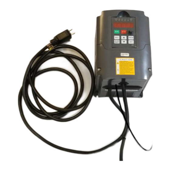
- Page 4 1. Unplug VFD power supply cord. ( It’s OK to leave the power cable connected to the top of the spindle.) 2. Remove the lower front cover from the VFD. DRAFT 3 06 09 2021...
- Page 5 3. Move jumper to the VI (left) position. DRAFT 3 06 09 2021...
- Page 6 4. Use a small screwdriver to loosen terminals DCM, ACM, RS- and RS+ DRAFT 3 06 09 2021...
- Page 7 5. Push the tail end of the speed control cable through the round grommet in the bottom of the VFD. TIP: Folding down the loose wire ends simplifies this step. DRAFT 3 06 09 2021...
- Page 8 Jumper wire Green wire 6. Connect the jumper wire between terminals DCM and ACM 7. Connect green wire to terminal ACM 8. Connect black wire to RS- 9. Connect red wire to RS+ 10. Tighten terminal connections and check that the new wires can’t be pulled out. DRAFT 3 06 09 2021...
- Page 9 11. Zip tie the Spindle cable to the other cable. Trim the zip tie. DRAFT 3 06 09 2021...
- Page 10 12. Reattached front panel. DRAFT 3 06 09 2021...
- Page 11 110 V Power Display glows red when 13. Plug VFD power cord into 110V outlet powered ON DRAFT 3 06 09 2021...
- Page 12 14. Press the “PRGM” button until 15. Press the up or down arrow to go the display reads Pdxxx. up or down the Program registry. NOTE: If no action is taken within a few seconds, the display will revert back to the normal/default view.
- Page 13 17. Press the SET button to access 16. Press required arrow until the the settings window for Pd001. Program registry number reads Pd001 DRAFT 3 06 09 2021...
- Page 14 19. Press the SET button to save the 18. Press the arrow buttons as setting. END will display when setting needed to change the setting for has been saved. Pd001 to _ _ _ _ 2. DRAFT 3 06 09 2021...
- Page 15 20. Repeat the process for the registry numbers listed below. NOTE: Some settings may already match the numbers below and do not need to be changed. CAUTION: Do not change any other settings. Doing so may damage your spindle. Reg. # New setting PD001 →...
- Page 16 21. Unplug VFD 22. Connect the Spindle Speed interface cable to port on the front of the control box. The tab on the top of the interface cable plug should face up when inserting it into the port. DRAFT 3 06 09 2021...
- Page 17 23. Update your Control Box Firmware per this link: www.nextwavecnc.com/firmware Controller Firmware version v4.5.x.x or higher is required. 24. Update your VCarve/Aspire post processor per this link: www.nextwavecnc.com/postprocessor 25. RPM settings from VCarve/Aspire will now be saved in your .tap file. When you run the .tap file the spindle will now automatically turn on and run at the RPM speed that was set for that toolpath in VCarve/Aspire.
- Page 18 DRAFT 3 06 09 2021...
Need help?
Do you have a question about the SHARK and is the answer not in the manual?
Questions and answers