Table of Contents
Advertisement
Quick Links
Solar Irradiation Sensor (Modbus RS485 Output) - Operation and Installation Manual
Models -MBMet-500AB, MBMet-500BB, MBMet-500CB and MBMet-500DB
Contents
Contents ............................................................................................................................................................ 1
1.
Warnings .................................................................................................................................................... 2
2.
Technical Specifications Solar Irradiation Sensor ...................................................................................... 3
3.
Parts of Solar Irradiation Transducer ......................................................................................................... 5
4.
Solar Irradiation Transducer- Installation ................................................................................................. 6
5.
Solar Irradiation Sensor - Connections ..................................................................................................... 8
6.
MBMet-500: - Default Configuration ........................................................................................................ 9
7.
MODBUS Registers .................................................................................................................................... 9
7.1
MODBUS Registers: ............................................................................................................................ 9
7.2
Configuration of MODBUS Communication Parameters ................................................................. 10
7.3
Setting Default MODBUS Communication Parameters ................................................................... 12
8.
General Maintenance .............................................................................................................................. 13
For service support call us on +91 33 65651011 or mail us in
Document Number:
(Suitable for HW Version-101 and SW Version - 101)
M4 050 020 010 01 (R1)
service@mbcontrol.com
1
Advertisement
Table of Contents

Related Manuals for MB MBMet-500AB

Summary of Contents for MB MBMet-500AB
-
Page 1: Table Of Contents
Solar Irradiation Sensor (Modbus RS485 Output) - Operation and Installation Manual Models –MBMet-500AB, MBMet-500BB, MBMet-500CB and MBMet-500DB Document Number: M4 050 020 010 01 (R1) (Suitable for HW Version-101 and SW Version – 101) Contents Contents ................................1 Warnings ..............................2 Technical Specifications Solar Irradiation Sensor .................. -
Page 2: Warnings
Warnings Installation at site should be done by skilled and qualified personal after taking required approvals. Use proper protection gear and tool while installing the device. Be aware of your surroundings while doing the installation work. Serious injury can occur if proper safety norms are not followed. -
Page 3: Technical Specifications Solar Irradiation Sensor
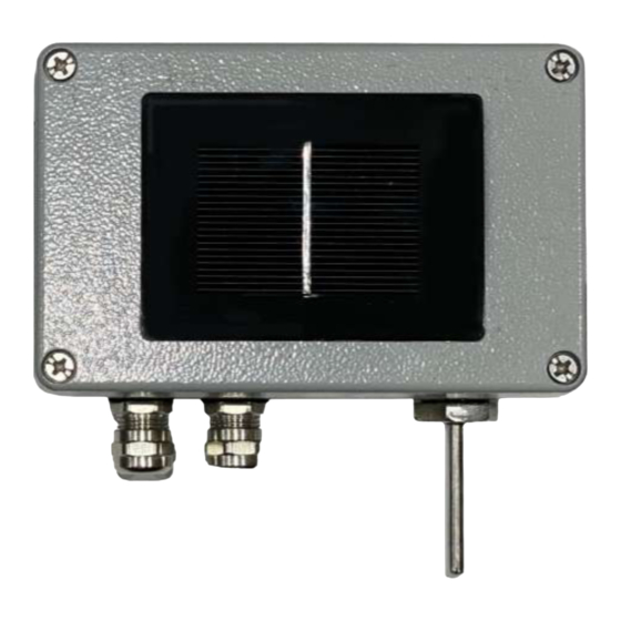
Technical Specifications Solar Irradiation Sensor Technical specifications for the Solar Irradiation sensor are provided in table-2.1 below. Model/ Parameters MBMet-500AB MBMet-500BB MBMet-500CB MBMet-500DB Output signal RS485 Modbus Sensor Silicon Power Supply 9-32 VDC Power Consumption 100mW Solar Irradiation Range 0-1500 W/m2 Accuracy ±5 W/m2 ±3 % of reading... - Page 4 General specifications are provided in table 2.2 below: Parameter Specification Irradiation Sensor Enclosure Cast Aluminum Ingress Protection IP65 120 (L) x 76 (W) x 65 Irradiation Sensor Enclosure Size (H) mm Weight 350 grams (approx.) Mounting clamp (suitable for mounting on PV module side) SS 304 Cable terminals 1.5 sq.
-
Page 5: Parts Of Solar Irradiation Transducer
SS Spring Clip for Temperature sensor mount Mounting Plate (SS-304) M5 X 32mm SS Hex Screw M5 SS Washer M5 Spring Washer M5 SS Nut M5 X 20mm SS Round Screw Table-3.1: Parts shipped with MBMet-500. Fig-3.1: MBMet-500AB Parts Fig-3.2: MBMet-500BB Parts... -
Page 6: Solar Irradiation Transducer- Installation
Fig-3.3: MBMet-500CB Parts Fig-3.4: MBMet-500DB Parts 4. Solar Irradiation Transducer– Installation Use the sensor mounting clamp provided along with the sensor to install it at side of the PV module (or any other location). Care must be taken that the sensor inclination is same as PV Module. - Page 7 Fig – 4.2: Mounting clamp position Step – 3: Open the cover of the sensor and mount the sensor to the clamp with the M5X20mm SS Round Head screws provided along with the sensor. The holes for mounting the sensor are shown in the figure 4.3. Fig –...
-
Page 8: Solar Irradiation Sensor - Connections
Care should be taken so that no components on the PCB are touched. Terminal numbers on the sensor PCB are given in the picture 5.1 below. Picture – 5.1: Terminal Numbers of PCB Connections for the transducer terminals are given in the table 5.1 below. Terminal MBMet-500AB MBMet-500BB MBMet-500CB MBMet-500DB... -
Page 9: Mbmet-500: - Default Configuration
6. MBMet-500: – Default Configuration Default configuration for solar irradiation sensor with RS485 output are shown in table-5 below. Sr. No Parameter Default Setting Communication Parameters Device MODBUS address Baud rate 9,600 Parity None Stop bits RTD Channel Temperature Unit Table-6: Default configuration for SmartBox 7. -
Page 10: Configuration Of Modbus Communication Parameters
0=4800; 1=9600; Integer 2=19200 Parity (Default: 0) Unsigned 0=None; 1=Odd; Read/Write Integer 2=Even Stop bits. Unsigned 1 (only stop bit 1 Read/Write Integer setting is allowed) Temperature Units Unsigned (Default: 0) Read/Write Integer C; 1 = K; 2 = Unsigned Save configuration Write only Integer... - Page 11 Data Type: 16 bits Integer Step-3: Set the communication parameters as per your requirement. (See example settings) MODBUS Register Parameter Example settings Address MODBUS ID 10 (Modbus ID=10) Baud rate 2 (Baud Rate = 19200) Parity 2 (Parity = Even) Stop bits 2 (Stop Bit = 2) Temperature Unit...
-
Page 12: Setting Default Modbus Communication Parameters
Setting Default MODBUS Communication Parameters Procedure for re-setting default communication parameters is as follows. Step-1: Switch Off the power supply of the device. Step-2: Locate the Jumper-1 on the PCB as shown in Fig – 7.3.1. The normal position of the jumper is shown in Fig 7.3.2 Fig –... -
Page 13: General Maintenance
Step-3: Change the jumper position from Fig 7.3.2 to Fig 7.3.3 Fig – 7.3.3 Jumper position (for factory resetting) Step-4: Switch On power supply, wait for 30 sec and switch off the power supply Step-5: Reconnect the jumper in the original factory position as in Fig 7.3.2 Communication parameters is reset to default settings.
Need help?
Do you have a question about the MBMet-500AB and is the answer not in the manual?
Questions and answers