
Related Manuals for AXEN AXSPS-90

Summary of Contents for AXEN AXSPS-90
- Page 1 Swimming Pool Heat Pump Operation and Installation Manual - Models AXSPS: 34-180500-0 Language: English...
-
Page 2: Table Of Contents
TABLE OF CONTENT INTRODUCTION …………………………………………………………………………………………………………... …………………………………………………………………………………………………………………. This manual …………………………………………………………………………………………………………..The unit ..………………... SAFETY INSTRUCTIONS ………………………………………………………………………… ……………………………………………………………………………………………………………………….… Warning ………………………………………………………………………………………………………………………… Caution ITEMS INSIDE THE BOX …………………………………………………………………………………………….…… OVERVIEW OF THE UNIT ……………………………………………………………………………………….……… INSTALLATION …………………………………………………………………………………………….…..….…….….. …………………………………………………………………………………………….…..…….. 8 Installation information ……………………………………………………………………………….……………………… 8 Condition of installation ……………………………………………………………………………………….……….. -
Page 3: Introduction
INTRODUCTION This manual This manual includes the necessary information about the unit. Please read this manual carefully before you use and maintain the unit. The unit The swimming pool heat pump is one of the most economical systems to heat the swimming pool efficiently. -
Page 4: Safety Instructions
SAFETY INSTRUCTIONS To prevent injury to the user, other people, or property damage, the following instructions must be followed. Incorrect operation due to ignoring of instructions may cause harm or damage. Install the unit only when it complies with local regulations, by-laws and standards. Check the main voltage and frequency. -
Page 5: Caution
If there is no suitable, earthed wall socket available, have one installed by a recognized electrician. Do not move/repair the unit yourself. Before proceeding with any maintenance, service or repair work, the product must be isolated from the mains electrical supply. Only qualified personnel should carry out these tasks. Improper movement or repair on the unit could lead to water leakage, electrical shock, injury or fire. -
Page 6: Items Inside The Box
ITEMS INSIDE PRODUCT BOX Before starting the installation, please make sure that all parts are found inside the box. The Unit Box Item Image Quantity Swimming pool heat pump Operation and Installation Manual Accessories... -
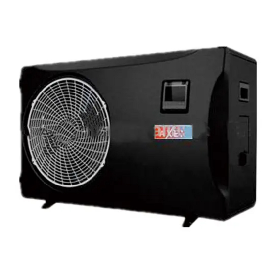
Page 7: Overview Of The Unit
OVERVIEW OF THE UNIT Outdoor Unit Dimension AXSPS- (outdoor unit) 147.5 157.5... - Page 8 Indoor Unit Dimension AXSPS- (indoor unit)
-
Page 9: Installation
INSTALLATION Installation information The following information given here is not an instruction, but simply meant to give the user a better understanding of the installation. Condition of installation The following information given here is not an instruction, but simply meant to give the user a better understanding of the installation. -
Page 10: Electrical Connection
Please refer to below table: Cable size Heat pump 3x4.0mm AXSPS-90 These data are only indication, you must ask an electrician to determine the exact data for your pool installation. Use the cable glands and grommets provided inside the heat pump to route cables. -
Page 11: Operating The Unit
OPERATING THE UNIT Operating the unit comes down to operating the digital controller. NEVER LET THE DIGITAL CONTROLLER GET WET. THIS MAY CAUSE AN ELECTRIC SHOCK OR FIRE. NEVER PRESS THE BUTTONS OF THE DIGITAL CONTROLLER WITH A HARD, POINTED OBJECT. THIS MAY DAMAGE THE DIGITAL CONTROLLER. -
Page 12: Buttons
Buttons Unit ON/OFF button Press this button when the unit is standby, the unit can be turned ‘ON’ and runs on the setting mode. The running mode, temperatures, timer situation and clock time are displayed on the screen. Press this button again when the unit is running, the unit then will be turned ‘OFF’. Mode button Press this button to select the running mode at any situation. -
Page 13: Controller Operations
In case when any malfunction occurs, this section will display the related error code. 6. Clock display The clock display shows the current time. When reading or programming the scheduled timer, the clock display shows the action time. 7. Timer ‘ON’ The icon indicates that the timer ‘ON’... - Page 14 3. Lock and unlock the buttons Press buttons at the same time and hold for 5 seconds, the buttons are locked after one buzzer sound. Press buttons at the same time and hold for 5 seconds again, the buttons are unlocked after one buzzer sound.
-
Page 15: Parameter Checking And Adustment
PARAMETER CHECKING AND ADUSTMENT Parameter list Some parameters can be checked and adjusted by the controller. Below is the parameter list. Content Scope Default Remark Return water setting temp. in 8-28℃ 27℃ Adjustable cooling Return water setting temp. in 15-40℃ 27℃... - Page 16 sensor open circuit Check the sensor connection PP01 Inlet water temp sensor failure sensor shot circuit Replace the sensor Main PCB damaged Replace the main PCB PP02 Outlet water temp sensor failure Same as above Same as above PP03 Coil temp sensor failure Same as above Same as above PP04...
-
Page 17: Maintenance
MAINTENANCE THE UNIT To protect the paintwork, avoid leaning or putting objects on the device. External heat pump parts can be wiped with a damp cloth and domestic cleaner. (Attention: Never use cleaning agents containing sand, soda, acid or chloride as these can damage the surfaces.) To prevent faults due to sediments in the titanium heat exchanger of the heat pump, ensure that the heat exchanger cannot be contaminated (water treatment and filter system necessary). -
Page 18: Troubleshooting
TROUBLESHOOTING This section provides useful information for diagnosing and correcting certain troubles which may occur. Before starting the troubleshooting procedure, carry out a thorough visual inspection of the unit and look for obvious defects such as loose connections or defective wiring. Before contacting your local dealer, read this chapter carefully, it will save you time and money. -
Page 19: Environmental Information
ENVIRONMENTAL INFORMATION This equipment contains fluorinated greenhouse gases covered by the Kyoto Protocol. It should only be serviced or dismantled by professional trained personnel. This equipment contains R410A refrigerant in the amount as stated in the specification. Do not vent R410A into the atmosphere: R410A, is a fluorinated greenhouse gas with a Global Warming Potential (GWP) = 1975. -
Page 20: Wiring Diagram
WIRING DIAGRAM Please refer to the wiring diagram on the electric box. Model: AXSPS-90 Outdoor Unit... - Page 21 Model: AXSPS-90 Indoor Unit...
-
Page 22: Technical Specifications
TECHNICAL SPECIFICATIONS Model AXSPS-90 capacity(KW) 9.11 power input(KW) 1.78 Air 15℃ Water 26℃ current(A) 8.59 5.12 capacity(KW) 7.98 Air 35℃ power input(KW) 2.21 Water 27℃ current(A) 10.19 3.62 power supply 220-240V / 50Hz max power inputKW 2.69 max currentA 12.5 water flow m³/h...
Need help?
Do you have a question about the AXSPS-90 and is the answer not in the manual?
Questions and answers