Table of Contents
Advertisement
Quick Links
Cold Thermostat Kit based on AC switches and ST7LITE MCU
Introduction
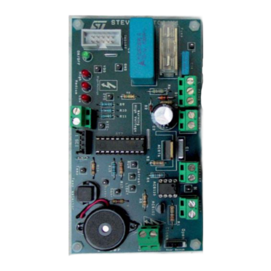
The STEVAL-IHT001V1 Thermostat Kit (figure below) is designed to control a refrigerator or
a freezer. This thermostat kit enables the control of a single-phase induction motor, a light
bulb and a defrost resistor (or a fan) working on 230 V
The board can operate in an ambient temperature range of 0 to 40 °C. The exact maximum
temperature depends on the power of the loads
The kit includes a Graphic User Interface (GUI) for sending commands to the ST7LITE39F2
Microcontroller or to access MCU information via the Serial Communication Interface (SCI).
This enables users to easily change MCU software parameters and acquire measurements
during appliance testing.
This document provides all the information needed to make the board work (how to connect
it, how it works). For specific information about modifying MCU parameters, please refer to
the "Help" section of the GUI software.
STEVAL-IHT001V1 Thermostat Kit
The main goals of this tool are:
●
Evaluate full ST solution (microcontroller + AC switch) for cold thermostat applications
●
Measure and save the appliance main parameters during operation (load status,
compressor operation duty cycle and running period, evaporator temperature)
●
Check and analyze efficiency gains by reducing the Hysteresis threshold or adapting
the defrost resistor management
●
Check the board immunity against fast transient voltages (without GUI connection).
August 2006
Getting started with the
50/60 Hz mains voltage.
RMS
(Section 3.1: Load
Rev 1
UM0277
User manual
power).
www.st.com
1/32
Advertisement
Table of Contents

Summary of Contents for ST STEVAL-IHT001V1
- Page 1 Cold Thermostat Kit based on AC switches and ST7LITE MCU Introduction The STEVAL-IHT001V1 Thermostat Kit (figure below) is designed to control a refrigerator or a freezer. This thermostat kit enables the control of a single-phase induction motor, a light bulb and a defrost resistor (or a fan) working on 230 V 50/60 Hz mains voltage.
-
Page 2: Table Of Contents
Appendix B Wiring connections ........23 Appendix C STEVAL-IHT001V1 thermostat kit......24... - Page 3 UM0277 Contents Appendix D Bill of materials ......... 25 Appendix E Procedure to apply IEC 61000-4-4 bursts test.
-
Page 4: Kit Introduction
Package contents This package (Figure 1) includes the following items: ● A thermostat board (ref.: STEVAL-IHT001V1) ● A M2020 5k NTC thermistor from EPCOS (ref.: M2020/5k/A17) ● A CD-ROM, including products presentations and data-sheets, user manual, Application Notes and the GUI software. -
Page 5: Board Presentation
Kit introduction Board presentation Figure 2 shows the STEVAL-IHT001V1 board and the main components used on this board. Figure 2. Power board (top view) J 1 c o n n e c to r (A C m a in s ) -
Page 6: Functional Description
Then, to get back the temperature data, the MCU could use a numerical table. In the STEVAL-IHT001V1 board, a simple resistor has been added in series with the NTC in order to linearize its thermal response (refer to Appendix A). -
Page 7: Compressor Control
A PTC thermal resistor is used to switch off this winding after start-up. In the STEVAL-IHT001V1 thermostat kit, this PTC is not replaced by a TRIAC as proposed on our previous THERM01EVAL kit (refer to AN1354). -
Page 8: Hardware Features
Hardware features 2.3.1 ACS and ACST devices The STEVAL-IHT001V1 board embeds one ACS102-6TA, one ACS110-7SB2 and one ACST6-7ST switches. The datasheet of these devices can be found in our web site (go to www.st.com/thyristors). Table 1 sums up the main differences between ACS and ACST switches and traditional TRIACs. -
Page 9: St7Lite39F2 Microcontroller
UM0277 Functional description 2.3.2 ST7LITE39F2 microcontroller The MCU used in the thermostat kit is the ST7LITE39F2. It belongs to the ST7LITE39F2 MCU family. It embeds a large number of features at the minimum cost. The peripheral hardware requirements are then reduced to the minimum: ●... -
Page 10: Graphic User Interface (Gui)
Functional description UM0277 Table 3. Maximum output DC average currents Max. output DC current for typical Max. output DC current for worst capacitor application conditions application case 220nF 7.1mA 5.5mA 330nF 10.7mA 8.3mA 470nF 15.2mA 11.8mA 680nF 22.1mA 17.1mA 1µF 32.5mA 25.2mA 1.5µF... -
Page 11: Getting Started
UM0277 Getting started Getting started Load power Initially, there is no heat sink mounted on the TO220-AB of the ACST6-7ST device. In this case, Figure 2.1 of their datasheet shows that the maximum permanent allowed current is 1.5 A RMS, for an ambient temperature lower than 40 °C. If the ACST6-7ST must sink a higher current, or works at a higher temperature, a heat sink can be added. -
Page 12: Pulse Control
Getting started UM0277 Table 4. Measurement points Footprint Name Description Line Neutral +5V power supply (also connected to ACS/ACST cathodes) GND power supply Zero Voltage Signal at MCU Input NTC- NTC value at MCU Input Gate control of the ACST6 (compressor) at MCU Output LIGHT Gate control of the ACS102 (light bulb) at MCU Output DEFROST... -
Page 13: Getting Started
No insulation is ensured between the accessible parts and the high voltage. The STEVAL-IHT001V1 Kit must be used with care and only by persons qualified for working with electricity at mains voltage levels. All measurement equipment must be isolated from the mains before powering the board. -
Page 14: Using The Gui Software
3.4.1 Using the GUI software In order to use the GUI of our STEVAL-IHT001V1 kit, a recent version of Windows®, such as Windows 98, Windows 2000 or Windows XP must be installed on your computer. The version of the Windows OS installed on your PC may be checked by clicking on the “System”... - Page 15 UM0277 Getting started Figure 8. Interface board Perform the following start-up procedure for the GUI: Connect the insulated PC interface board to the PC via the RS232 Interface cable and to the thermostat board via the SCI Interface wire. Connect the 230V/9V insulated power supply to the SCI interface board. First check that the 230V/9V insulated power supply is correctly set: the Volt switch to the “9V”...
-
Page 16: Gui Windows Description
Getting started UM0277 Figure 9. 230V/9V insulated power supply configuration GUI windows description 3.5.1 Temperature control Use the “Thermostat Order” switch position on the GUI (Figure 10) or the “Temp Selector” push button on the board to select the correct temperature order. Note: ●... -
Page 17: Timing Control
UM0277 Getting started Figure 10. Temperature control tab 3.5.2 Timing control The Timing Control tab (Figure 11) controls the gate current width for the TRIACs, the delay to switch ON the TRIACs Q1 (for compressor), the ZVS delay, the delay to activate defrost and the defrost duration. -
Page 18: Force Debug
Getting started UM0277 measured to switch ON the TRIACs which controls the Light Bulb and the Defrost resistor is approximately 130µs for the AC mains negative cycle (230 V 50 Hz line). The maximum delay measured to switch ON the compressor is approximately 170µs for the AC mains negative cycle (see Figure 12). -
Page 19: Parameter Measurements
UM0277 Getting started Figure 13. Force debug tab 3.5.4 Parameter measurements The GUI can detect and display all the various parameters of the MCU, such as the temperature order, the evaporator temperature, the AC load states, the compressor cycle information (running period and duty cycle) and the Mains frequency. For more information, refer to the “Help”... -
Page 20: Conclusion
Conclusion UM0277 Conclusion This document will help cold-appliance designers to use our STEVAL-IHT001V1 thermostat kit to: ● Check the immunity of this ST solution ● Easily check the efficiency gains by hysteresis threshold reduction ● Define the better management of the defrost cycles to improve the overall efficiency ●... -
Page 21: Appendix A Thermal Sensor Linearization
UM0277 Thermal sensor linearization Appendix A Thermal sensor linearization An NTC thermistor is a thermal resistor whose value decreases when its temperature increases. The thermal law is exponential, as presented in Equation Equation 1 ⎛ ⎞ • -- - – ------ - ⎝... - Page 22 Thermal sensor linearization UM0277 Figure 14. Linear voltage response of the NTC thermistor (for a 5V supply) 22/32...
-
Page 23: Appendix B Wiring Connections
UM0277 Wiring connections Appendix B Wiring connections For the NTC thermistor, you just have to connect its terminals to the “NTC” connector. Its wires can be connected in any way as it is just a resistor. The same procedure can be achieved for the Light Bulb and Defrost resistors. For the motor, things are more complex. -
Page 24: Appendix Csteval-Iht001V1 Thermostat Kit
STEVAL-IHT001V1 thermostat kit UM0277 Appendix C STEVAL-IHT001V1 thermostat kit Figure 17. STEVAL-IHT001V1 evaluation board schematic diagram 24/32... -
Page 25: Appendix D Bill Of Materials
UM0277 Bill of materials Appendix D Bill of materials Table 5. Bill of materials Name Designation Comment Resistor 33 Ohm−1/2W - 5% Resistor 51 Ohm-1/4W - 5% Resistor 150 Ohm-1/4W - 5% Resistor 130 Ohm-1/4W - 5% Resistor 390 Ohm-1/4W - 5% Resistor 47 Ohm -1/2W - 5% Resistor 150 kOhm-1/4W - 5% Resistor 150 kOhm-1/4W - 5%... - Page 26 Bill of materials UM0277 Table 5. Bill of materials (continued) Name Designation Comment Zener 5V6 - 0.5W Rectifier 1N4148 Led1 Red LED / 7mA High temperature order Led2 Green LED / 7mA ON/OFF state Led3 Red LED / 7mA Medium temperature order Led4 Red LED / 7mA Low temperature order...
- Page 27 UM0277 Bill of materials Table 5. Bill of materials (continued) Name Designation Comment STRAP STRAP Length is given from pad to pad STRAP J6/J7/J8/J9 Corner Spacer: Screw J6/J7/J8/J9 Corner Spacer: Nut Fuse Fuse 5x20mm 8A 250V Fuse socket Socket hood 27/32...
-
Page 28: Appendix E Procedure To Apply Iec 61000-4-4 Bursts Test
Procedure to apply IEC 61000-4-4 bursts test UM0277 Appendix E Procedure to apply IEC 61000-4-4 bursts test To perform fast transient voltage tests in compliance with EN61000-4-4 specifications on thermostat boards connected to a compressor, a 15W light bulb and a 25W defrost resistor, we have implemented the arrangements shown in Figure 18. -
Page 29: Appendix Fpc Interface Parameters Description
UM0277 PC interface parameters description Appendix F PC interface parameters description Table 6. PC interface parameters description Initial Setting Parameter Software type Unit Allowed range setting step Temperature Hysteresis Input / Output °C 0.5 to 10°C Thermostat order Input / Output 1 to 3 Evaporator temperature order 1 Input / Output... -
Page 30: Appendix G Capacitor Value According To Country
Capacitor value according to country UM0277 Appendix G Capacitor value according to country Table 7 indicates the capacitor value for a 30mA average current for typical application case (nominal capacitor value, nominal RMS line voltage) versus different AC mains and frequency values used in different countries. -
Page 31: Revision History
UM0277 Revision history Revision history Table 8. Document revision history Date Revision Changes 28-Aug-2006 Initial release. 31/32... - Page 32 No license, express or implied, by estoppel or otherwise, to any intellectual property rights is granted under this document. If any part of this document refers to any third party products or services it shall not be deemed a license grant by ST for the use of such third party products or services, or any intellectual property contained therein or considered as a warranty covering the use in any manner whatsoever of such third party products or services or any intellectual property contained therein.
Need help?
Do you have a question about the STEVAL-IHT001V1 and is the answer not in the manual?
Questions and answers