Advertisement
Quick Links
STEREO INTEGRATED AMPLIFIER/TUNER
C-V301/V351
SERVICE MANUAL
Indicator
Front glass
(B12-0311-04)
(B10-2350-14)
623
ON/STANDBY
PHONES
INPUT
682
J1
Phone jack
Knob
(E11-0280-05)
(K29-6665-02)
Lock terminal board
(E70-0052-05)
J2
AM
ANTENNA
FM 75Ω
GND
SYSTEM
CONTROL
CONNECT WITH
POWER AMPLIFIER
J7
Rectangular receptacle
Miniature phone jack (2P)
(E58-0018-05)
(E11-0293-05)
Caution : No connection of ground line if disassemble the unit.
Please connect the ground line on rear panel, PCBs, Chassis and some others.
Knob
(K29-7601-02)
683
624
TIMER
SET
CLOCK
TIMER
RDS
MODE
S.DIRECT
DISPLAY
PTY
TA/NEWS/INFO.
TAPE 2
(MONITOR)
Metallic cabinet
Phono jack
(A01-3431-01)
(E63-0163-05)
601
J3
MONITOR
OUT
TAPE 2
/DVD
AUX
TAPE 1/ MD
CD
(MONITOR)
L
R
IN
IN
REC
PLAY
REC
PLAY
J5
J123
Phono jack
(E63-0139-15)x3
Knob
(K29-7591-02)
681
MODE
MULTI.CONTROL
STEREO
DSP
LEVEL
PTY SELECT
A.MEMO
AUTO
BAND
TUNING
AV CONTROL CERTER KC-2
Phono jack
AC power cord *
(E63-1005-05)
(E30-)
J2
650
VIDEO
LD
VCR
DVD 6CH.INPUT
CENTER
IN
REC
PLAY
FRONT
SURROUND
SUBWOOFER
AUDIO
J4
Phono jack
(E63-1084-05)
* Refer to parts list on page 25.
© 1999-7/B51-5556-00 (K/K) 1653
Front glass
Panel
(B10-2351-14)
(A60-1696-11)
620
609
VOLUME CONTROL
OPEN/CLOSE
DOWN
UP
682
680
Knob
Knob
(K29-6665-02)
(K29-6660-04)
Power cord busing
(J42-0083-05)
678
UNSWITCHED
J6
AC outlet *
(E03-)
70%
Advertisement

Related Manuals for Kenwood CV-351-HU


Summary of Contents for Kenwood CV-351-HU
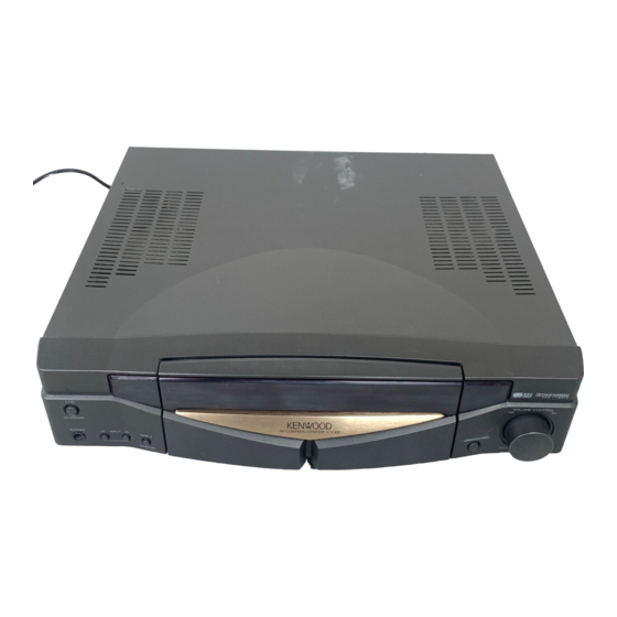
- Page 1 STEREO INTEGRATED AMPLIFIER/TUNER C-V301/V351 SERVICE MANUAL © 1999-7/B51-5556-00 (K/K) 1653 Indicator Front glass Knob Knob Front glass Panel (B12-0311-04) (B10-2350-14) (K29-7601-02) (K29-7591-02) (B10-2351-14) (A60-1696-11) TIMER MODE MULTI.CONTROL CLOCK STEREO LEVEL TIMER PTY SELECT A.MEMO AUTO BAND MODE S.DIRECT DISPLAY TA/NEWS/INFO. TUNING VOLUME CONTROL AV CONTROL CERTER KC-2...
-
Page 2: Table Of Contents
C-V301/V351 CONTENTS / ACCESSORIES / CAUTIONS Contents CONTENTS / ACCESSORIES / CAUTIONS..... 2 SCHEMATIC DIAGRAM .......... 11 DISASSEMBLY FOR REPAIR........3 EXPLODED VIEW ............24 ADJUSTMENT ............4 PARTS LIST..............25 PC BOARD ..............5 SPECIFICATIONS ........Back cover Accessories Graphical Remote Control unit (1) FM indoor antenna (1) AM loop antenna (1) (T90-0833-05) (C-V351) -
Page 3: Disassembly For Repair
C-V301/V351 DISASSEMBLY FOR REPAIR 1. Remove the 1 screw (1), Then pull the slider (2) till last 2. While raise the slider of left side, remove the slider from the bosses (3,4) -
Page 4: Adjustment
C-V301/V351 ADJUSTMENT INPUT OUTPUT TUNER/AMP ALIGNMENT ITEM ALIGN FOR FIG. SETTING SELECTOR SETTING POINTS SELECTOR : FM Connect a DC voltmeter between L31 (X05-) DISCRIMINATOR 98.0MHz AUTO port of CN2 1kHz, ±40kHz dev 98.0MHz (E, T type) (E, T only) Minimum 60dBu (ANT INPUT) L32 (X05-) -
Page 5: Pc Board
PC BOARD (Component side view) (X13-7562-70) Refer to the schematic diagram for the value of resistors and capacitors. - Page 6 PC BOARD (Component side view) Refer to the schematic diagram for the value of resistors and capacitors.
- Page 7 PC BOARD (Component side view) Refer to the schematic diagram for the value of resistors and capacitors.
- Page 8 DISCRI (X05-468X-XX) CAUTION: For continued safety, replace safety critical components only with manufacturer's recommended parts (refer to parts list). indicates 8.3V safety critical components. For continued protection against risk of fire, +15V 5.6K replace only with same type and rating fuse(s). To reduce the risk of 14.5V 2.2K DET-OUT...
- Page 9 WH10 to M-A100 M-A300 CONTROL UNIT (X11-37XX-XX) (A/5) CN16 10 9 C199 220P C196 220P Lch 1 R303 R96 10 C197 220P R99 10 Rch 2 X5 8MHz R97 10 TP-S C198 220K 220P R98 10 R100 10 4.7Kx11 Lch 3 REMOTE 4.5V u-COM...
- Page 10 X08-A/2 -CN2 C-V301/V351 DESTINATION UNIT No. D14 D15 COUNTRY ABB. U.K. X11-3730-53 YES NO EUROPE X11-3732-73 NO YES X13-SUB D1-6,13-16,29,30,32,37-39,44-46, : NJU7312AL Q1,2 : 2SC2878(B) -CN2 48,54-60 : 1SS131 or HSS104A : NJU7311AL : 2SB1370(E,F) or 2SB1375 : RD5.6ES(B2) or HZS5.6N(B2) : NJM4565D-D Q10,13,16,19 : 2SD2061...
- Page 11 PRE AMP UNIT X11-A/5 -CN16 (X08-2672-73) (A/2) +15V VMUTE 15 C81 2.2u50 VSEL2 EBOL.CK C82 2.2u50 X11-A/5 EBOL.DATA +10dB 11 -6dB 5.0V -15V +15V +15V +15V C133 AGND 1000P IC10 -15.4V SW3’ C131 10P VSEL1 1 R139 TC9215 X11-A/5 R155 -CN17 5.6K GND 5...
- Page 12 2SC2003 DTC124ESA UN5119 2SB1370 UN4212 2SC2878 2SA1048 2SA1576A 2SD2061 2SA1309A (X08- ) (B/2) 2SC3246 2SC2458 2SA1586 2SC3311A PHONES SUB UNIT 2SC4116 R119 (X13-7562-70) 14.8V +15V 100 2W IC5(1/2) MUTE ON: 2.0V C61 1u50 C69 1u50 15.0V MUTE OFF: -9.3V R111 (2/2) +15V R103...
- Page 13 X11-A/5 DISPLAY UNIT (X14-4372-71) (D/4) SUB UNIT (X13-7522-71) X11-A/5 INFO. MEMO AUTO PRO LOGIC TAPE2 R51 47K 2.8V NEWS 2.5V STEREO R56 220 3 STEREO MIC GND SOURCE RDDATA 2.2K DIRECT 2.2u50 OSCO TUNED VREF 2.0V 2.5V TIMER 330P OSCI EX.BASS SLEEP MUTE...
- Page 14 UNSWITCHED TOTAL 100W MAX X13-7562-70 AC 230V~50Hz X13-7522-71 (B/5) X08-2762-73 ANTENNA (A/2) X05-4682-71 J 3 J 2 VIDEO (E/5) (C/5) X11-3732-73 (A/5) (D/5) X14-4372-71 (A/4) (C/4) (B/2) DVD 6CH LD/DVD. CD. ADX. SYSTEM TAPE2 TAPE1 INPUT CONTROL J 4 J 3 J 2 J 1 J 5 J 7 (B/4) CONNECT WITH POWER AMP.
- Page 15 New Parts New Parts Parts without Parts No. are not supplied. Parts without Parts No. are not supplied. Les articles non mentionnes dans le Parts No. ne sont pas fournis. Les articles non mentionnes dans le Parts No. ne sont pas fournis. Teile ohne Parts No.
- Page 16 New Parts New Parts Parts without Parts No. are not supplied. Parts without Parts No. are not supplied. Les articles non mentionnes dans le Parts No. ne sont pas fournis. Les articles non mentionnes dans le Parts No. ne sont pas fournis. Teile ohne Parts No.
- Page 17 New Parts New Parts Parts without Parts No. are not supplied. Parts without Parts No. are not supplied. Les articles non mentionnes dans le Parts No. ne sont pas fournis. Les articles non mentionnes dans le Parts No. ne sont pas fournis. Teile ohne Parts No.
- Page 18 New Parts New Parts Parts without Parts No. are not supplied. Parts without Parts No. are not supplied. Les articles non mentionnes dans le Parts No. ne sont pas fournis. Les articles non mentionnes dans le Parts No. ne sont pas fournis. Teile ohne Parts No.
- Page 19 New Parts New Parts Parts without Parts No. are not supplied. Parts without Parts No. are not supplied. Les articles non mentionnes dans le Parts No. ne sont pas fournis. Les articles non mentionnes dans le Parts No. ne sont pas fournis. Teile ohne Parts No.
- Page 20 New Parts New Parts Parts without Parts No. are not supplied. Parts without Parts No. are not supplied. Les articles non mentionnes dans le Parts No. ne sont pas fournis. Les articles non mentionnes dans le Parts No. ne sont pas fournis. Teile ohne Parts No.
- Page 21 New Parts HOW TO READ THE PARTS LIST Parts without Parts No. are not supplied. Destination column has the abbreviation for sale country and model. Les articles non mentionnes dans le Parts No. ne sont pas fournis. Teile ohne Parts No. werden nicht geliefert. Alphabets mean the country.
-
Page 22: Specifications
Frequency response ..... 30 Hz~15 kHz, + 0.5 dB, – 3.0 dB 1. KENWOOD follows a policy of continuous advancements in development. For this reason specifications may be changed without notice. 2. Full performance may not be exhibited in extremely cold locations (below 0 deg.C).
Need help?
Do you have a question about the CV-351-HU and is the answer not in the manual?
Questions and answers