Advertisement
mach-engineering.com
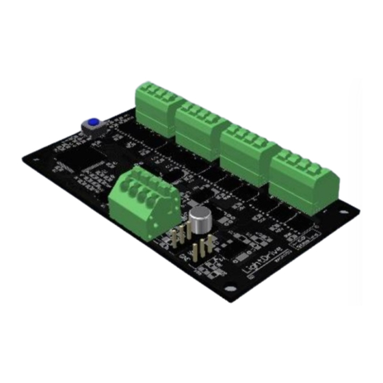
LightDrive 12 – LED Controller
Thank you for purchasing the LightDrive 12 LED controller. The LightDrive is a
very powerful controller built onto a tiny footprint. This guide is meant to give you a good idea of the
LightDrive's capabilities and limitations. After that, it's up to you.
The LightDrive can be controlled several different ways. The user may choose between CANbus, TTL Serial,
and R/C PWM inputs. These methods offer different advantages:
Color Depth
Update Rate
Physical
Signal
Format
For detailed information on these protocols, see Appendix A. The LightDrive will switch automatically to the
proper protocol based on which signal it sees. If more than one is present, the LightDrive will choose a
protocol in the following order: Serial -> CAN -> PWM. Example code, including an API, is available for the
FRC RoboRIO controller in C++, Java, and LabView. Simply use the appropriate API for whichever control
method you want to use (PWM, CAN, Serial).
Connection Diagram
CAN
Port
- Connect H and L
- Connect anywhere in
the chain with other
devices
Serial
Port
- Connect GND and TXD
- RXD Optional if feedback
is not needed
Rev 2002
R/C PWM
CAN
'3 bit' – 8 Colors
Full 24bit – 8bit x 12ch
0.8Hz – 1ch/100ms
10Hz – 12ch/100ms
2 R/C PWM Inputs
2-Wire CAN Input
0.5-2.5ms width
1Mbit CAN
50/125/250Hz
Choose One of These 3 Methods
LightDrive User Guide
User Guide
TTL Serial
Full 24bit – 8bit x 12ch
10Hz – 12ch/100ms
TTL Serial Input
115.2kBaud 8N1 Serial
R/C PWM Outputs
- Connect to Any 2
1
Advertisement
Table of Contents

Related Manuals for Mach LightDrive 12

Summary of Contents for Mach LightDrive 12
- Page 1 LightDrive 12 – LED Controller User Guide Thank you for purchasing the LightDrive 12 LED controller. The LightDrive is a very powerful controller built onto a tiny footprint. This guide is meant to give you a good idea of the LightDrive’s capabilities and limitations.
- Page 2 Basic Operation 1. Connect the LightDrive as shown in the diagram. LED Outputs Onboard User Pushbutton Signal R/C PWM Inputs +12V CANL CANH Data In Serial Input Data Out 2. Apply Power a. The LightDrive will display a test-pattern, then become ready after 1 second. b.
- Page 3 Specifications and Notes Specifications Size 2.0x3.5in (50.8x88.9mm) Refresh Rate 100Hz for all channels Input Voltage 8 – 16VDC Power Connector 16-24AWG Screwless Max Current Lesser of 15A or 5A/output RC Connector 3pos 0.1in Male HDR PWM Inputs 20-250Hz 0.5-2.5ms (GND-6V*-SIG) *6V Connection optional CAN Input 1Mbit/s...
- Page 4 3. Paste the following URL: http://mach-engineering.com/products/maven/com/mach/LightDrive/LightDrive.json C++/Java Programming Once the above has been completed, add the needed import statements to your program: //Java import com.mach.LightDrive.*; //The LightDrive Library import java.awt.Color; //Predefined colors and routines //C++ #include “LightDrive.h” Now, create your desired LightDrive object:...
- Page 5 LabView Programming Using the LabView VIs from mach-engineering.com, create a diagram as below. Each time the surrounding frame is called, the values will be pushed to the LightDrive. Rev 2002 LightDrive User Guide...
- Page 6 Appendix A – Protocols TTL Serial Protocol Using the serial protocol, all 12 channels can be set to any level from 0-255. If desired, the RX line can be connected to get feedback from the LightDrive. The serial format is 8N1 (8-bit, no parity, 1 stop bit) at 115.2kBaud.
Need help?
Do you have a question about the LightDrive 12 and is the answer not in the manual?
Questions and answers