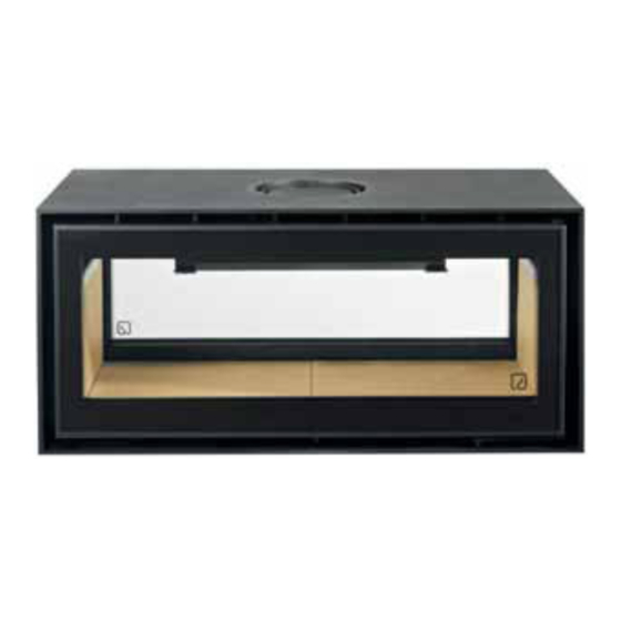
Advertisement
Quick Links
Fan Installation Manual
For LINEA – NMV
Inbuilt Appliances
VARIABLE SPEED CONTROLLER
Supplied by:
Castworks Pty Ltd
57 Industrial Drive
Braeside VIC 3195
Warnings
Danger of Electrocution: All electrical work must be carried out by a qualified electrician.
Note: All electrical components should be installed in an airy location away from hot parts
Advertisement

Summary of Contents for ADF LINEA NMV
- Page 1 Fan Installation Manual For LINEA – NMV Inbuilt Appliances VARIABLE SPEED CONTROLLER Supplied by: Castworks Pty Ltd 57 Industrial Drive Braeside VIC 3195 Warnings Danger of Electrocution: All electrical work must be carried out by a qualified electrician. Note: All electrical components should be installed in an airy location away from hot parts...
- Page 2 IMPORTANT: • Must be installed in accordance with AS/NZS 3000. • Must be installed to the manufacturers’ specifications. • Power supply must be installed by a licensed electrician. • If the power cables are damaged, for any reason, do not use. Have the cord replaced immediately.
- Page 3 1. Operation of the Controller (User Manual) Control Panel, Use and Functions ON/OFF Fan Speed Exit the Menu Menu Scroll Fan Speed MENU Down, Enter Menu User Scroll Menu Probes Menu The Temperature of the Manual Control Setting Heater Thermostat (°C) Temp.
- Page 4 20°C change in temperature. Once chosen, to save the Preferred Selected speed, press the ON button, or wait 5 seconds. 2. To go into the Main Menu, hold the Menu button for 3 seconds. Press the Menu button to scroll through setting options. Press the UP and DOWN button to change the value.
-
Page 5: Installation Instructions
Installation Instructions Warning Danger of Electrocution: All electrical work must be carried out by a qualified electrician. Note: All electrical components should be installed in an airy location away from hot parts. Make sure that the Main Power Supply is OFF prior to installing the device. 1. - Page 6 3. Connect the controller to the Ventilation Kit Electrical connecting diagram for the back of the Wall Mounted Controller • 240V supply attaches to position 1 (Neutral), and 2 (Live). • The cabling to the Fan attaches to 5 (Neutral) and 6 (Live). •...
- Page 7 Wiring layout on back of Controller: Earth wiring using Blue Connector:...
- Page 8 Wiring completed on back of Wall controller: 1 And 5 Wires – BLUE 2 And 6 Wires – BROWN Wires through Join, Earth = Yellow and Green stripe...
- Page 9 Access to Fan Remove ash retainer by lifting it upward slightly to clear the base brick, then rotating it forward (below) and finally pulling out diagonally by lifting one side higher and out.
- Page 10 Remove the vermiculite base bricks from the floor of the firebox. Undo the screws and remove the fan access cover (flat steel plate).
-
Page 11: Install The Fan
Install the Fan The controller must be positioned away from vents or the heat source, where it won’t get too hot. A minimum of 200mm from either side of the firebox. Do not place above the firebox. Remove the bottom plate from the outer body, by tapping with a hammer to break the perforation ties. - Page 12 Now install the fan by slotting it into the cut out inside the firebox, with the grill intake facing towards the front. Ensure there is NO Gap in the Top between the fan and the heater.
- Page 13 Position must be as below, with the tab on the rear of fan casing, so that it sits on the heater on the fold “shelf” at the rear. Fix the fan in position with 2 screws on each end.
-
Page 14: Fitting The Thermostat
Fitting the Thermostat. Fit the thermostat to the underside of the Fan access cover. This is for Versions MANUFACTURED from February 2020 with the Tab like below fixed to the bottom of the firebox plate. Use the hole closest to the heater. For appliances built before February 2020, use the supplied adaptor bracket, to fix below the Thermostat tabs on the underside of the firebox, and fit the thermocouple wire to the adaptor bracket. - Page 15 Replace the cover for Fan Access. When inserting, ensure that the thermostat cabling is fixed in position so it cannot move and rub or get caught in the fan blades. Besides being noisy, this could damage the cables, the blades or the fan. Use cable ties if required (not supplied). Screw the cover back into position.
- Page 16 9. INSTALLER MENU FOR ADJUSTING CONTROL PARAMETERS Only Qualified Personnel must access this MENU, because changing the set of parameters could make the product completely unsuitable for the application. • To enter this Menu, Press the MENU and DOWN button at the same time for 3 Seconds. •...
- Page 17 9.1 SERVICE OUTPUT SERVICE is Programmable from the Installer Manual by using parameter P02: P02 = 0 DISABLED: the output does not work. P02 = 1 THERMOSTAT: the output is activated if the temperature of S1 probe is above Thermostat E07 P02 = 2 GRILL: press for 3 seconds K3 key to turn on/off the output P02 = 3 AIR DAMPER: this output is used to manage an Air Damper to adjust for Combustion Air Flow 9.2 AIR DAMPER...
- Page 18 Imported By: Manufactured by: Castworks, A.D.F. Lda. 57 Industrial Drive, Z.I. Relvinha, Sarzedo A.P. 55 Braeside, Vic 3195 3304-909 Arganil-Portugal 02/04/2020...
Need help?
Do you have a question about the LINEA NMV and is the answer not in the manual?
Questions and answers