Table of Contents
Advertisement
Quick Links
Advertisement
Table of Contents

Summary of Contents for Ceasefire INTELLI-SENSE
- Page 1 INSTALLATION, COMMISSIONING & OPERATING MANUAL FOR NETWORKING TI-002324/002325...
- Page 2 Installation and Commissioning Manual CFX-Plus Intelli-Sense Networking This application note describes how install and configure Intelli-Sense Networks.
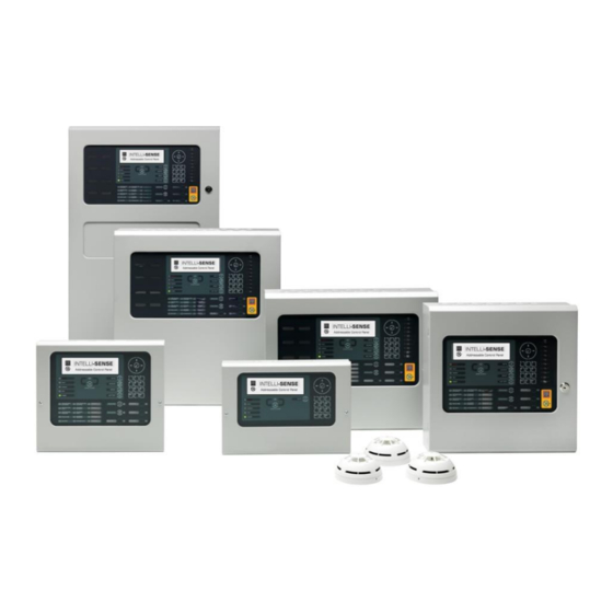
- Page 3 The Network cards are compatible with all Intelli-Sense series control panels. The Remote Terminals TI-002322/TI-002321/TI-002323, BMS/Graphics interface and other network peripherals such as Intelli-Sense Mimic Units (IMU) all have integral network cards built-in. (Only use fault tolerant Peripherals and Remote Terminals on a fault tolerant network).
-
Page 4: Table Of Contents
CONTENTS Table of Contents INTRODUCTION ..............................4 Key Features ............................... 4 Specifications .............................. 5 INSTALLATION ..............................6 Installing the Panel Network Card ....................... 6 Wiring Installation ............................6 Fault Tolerant Fibre Networks ........................8 CONFIGURATION AND PROGRAMMING ......................9 Initial Configuration ............................9 3.1.1 Configuring a Network from the PC ...................... -
Page 5: Introduction
1 Introduction The Intelli-Sense-NeT network is a true peer-to-peer token passing system that has been optimised for re systems. It allows larger buildings to be protected by distributing the re panels throughout the building, instead of having to take all the detection circuits back to a single point. -
Page 6: Specifications
ABOUT THIS PANEL 1.2 Specifications Item Specification Number of Zones 2000 Number Nodes Number of Sectors Where you see the “PC Only” symbol, these features can be either only set-up using the PC Configuration Tool or there are additional options that are only available via the PC Configuration Tool. -
Page 7: Installation
ABOUT THIS PANEL 2 Installation Isolate ALL sources of power before installing or removing printed circuit boards. Observe anti-static precautions at all times when handling printed circuit boards. 2.1 Installing the Panel Network Card An TI-002325 (STD) or an TI-002324 (FT) Network Card can be installed onto the base card. The card is fitted to the base card using 2x M3 screw and 2x... - Page 8 ABOUT THIS PANEL The network permits the connection of other panels, remote terminals and other devices to complete a distributed system. Either an TI-002325 (STD) standard network interface card or an TI-002324 (FT) fault tolerant network interface card must be installed in the panel. All network nodes must be installed with the same type of interface.
-
Page 9: Fault Tolerant Fibre Networks
A break in a fibre optic cable is shown between the transmit output of the fibre interface connected to node 4 and the receive input of the fibre interface connected to node 3 – refer to diagnostics section on how this fault is reported. Contact Ceasefire Sales / Technical Support for further information on available options. -
Page 10: Configuration And Programming
ABOUT THIS PANEL 3 Configuration and Programming 3.1 Initial Configuration TI-002319-VL Node 1 TI-002318-V Node 4 TI-002317-V Node 2 TI-002323 Node 3 A network can be configured either directly from the panel, or from a PC. The PC can give greater flexibility over displays, but the fundamental network principles remain the same. -
Page 11: Adding A Node To The Network
ABOUT THIS PANEL 3.1.2 Configuring a Network at the Panel Select the “SETUP” option from “[Commission Menu 2]”. [Setup] THIS NETWORK NODE NEXT NETWORK NODE PANEL ZONE : 1997 SERVICE NUMBER : 01234 56789 Enter the address of “THIS NETWORK NODE”. Always ensure this is unique for each node on the network (entering Node “0”... -
Page 12: Making Changes To A Panel
ABOUT THIS PANEL Configure the new node on the network by giving it a unique node address in the same way as when the network was first Add the new node at the end of the line. Remember the length of each cable should not exceed 1.5km. Overall loop length should not exceed 20km. -
Page 13: Diagnostics Tools
ABOUT THIS PANEL 4 Diagnostics Tools 4.1 Fault Tolerant Network Card Software version The version number of the firmware of the fault tolerant network card can be viewed. Navigate to the network diagnostics screen, and the version is shown in the upper right area of the screen, as shown below. This software version information can also be viewed using the VIEW –... -
Page 14: Panel Network Analyser
ABOUT THIS PANEL 4.3 Panel Network Analyser Each panel has a network analyser built into the panel circuits and software. It’s well worth using this analyser each time you add a new panel to the network. When you exit from commissioning, invoke the analyser by selecting from the “Level 2 Menu”... -
Page 15: Network Diagnostics - Duplicated Zones
ABOUT THIS PANEL 4.3.2 Network Diagnostics – Duplicated Zones A warning is produced if any of the panels that are active on the network appear to duplicate zones that have been assigned to this panel. For example, if both this panel and the panel at node 2 both have devices assigned to zone 19, a “Duplicated Zone”... -
Page 16: Network Diagnostics - Statistical Analysis
ABOUT THIS PANEL [NETWORK – Press 0 to Clear] More > Node State LEVEL 2 FT REVERSE RING FAULT LEVEL 2 FT REVERSE RING FAULT LOCAL FT RING LEVEL 1 FT REVERSE RING FAULT [NETWORK – Press 0 to Clear] More >... -
Page 17: Common Faults / Problems
ABOUT THIS PANEL 5 Common Faults / Problems 5.1 Corruption in the Transmission of Data The most likely reason is that the cabling is being subjected to external interference. This can be caused by a number of factors. For example: Non-screened cable used. -
Page 18: Recommended Cables
ABOUT THIS PANEL 6 Recommended Cables A 2-core twisted-pair cable is required between each Intelli-Sense-Net node. Choose a cable in accordance with the regulations and codes appropriate to the country and location of installation. The following is recommended if no other regulations apply.