Table of Contents
Advertisement
Quick Links
SUPERSEDES: September 23, 2010
ALM2 . . . . . . . . . . . . . . . . . . . . . . . . . . . . . . . . . . . . . . 3
Overview . . . . . . . . . . . . . . . . . . . . . . . . . . . . . . . . . 3
Features. . . . . . . . . . . . . . . . . . . . . . . . . . . . . . . . . . 3
Purpose of This Guide . . . . . . . . . . . . . . . . . . . . . . . . . 3
Representations and Warranties . . . . . . . . . . . . . . . . . 3
Applicable Documentation . . . . . . . . . . . . . . . . . . . . . . 4
Installation Instructions. . . . . . . . . . . . . . . . . . . . . . . . . 4
Precautions . . . . . . . . . . . . . . . . . . . . . . . . . . . . . . . . . 4
General . . . . . . . . . . . . . . . . . . . . . . . . . . . . . . . . . . 4
Static Electricity . . . . . . . . . . . . . . . . . . . . . . . . . . . . 4
Location . . . . . . . . . . . . . . . . . . . . . . . . . . . . . . . . . . 4
FCC Compliance . . . . . . . . . . . . . . . . . . . . . . . . . . . 5
Before Installing . . . . . . . . . . . . . . . . . . . . . . . . . . . . . . 5
About this Document . . . . . . . . . . . . . . . . . . . . . . . . 5
Inspecting the Equipment . . . . . . . . . . . . . . . . . . . . 5
What is Not Included with this Equipment . . . . . . . . 5
Equipment Location . . . . . . . . . . . . . . . . . . . . . . . . . 5
Selecting a Power Source . . . . . . . . . . . . . . . . . . . . 5
Installation . . . . . . . . . . . . . . . . . . . . . . . . . . . . . . . . . . 6
Mounting the Device . . . . . . . . . . . . . . . . . . . . . . . . 6
Routing Cabling to the Device . . . . . . . . . . . . . . . . . 7
Grounding the Device . . . . . . . . . . . . . . . . . . . . . . . 8
© 2010 Taco Electronic Solutions, Inc.
Application Guide
ALM2 Alarm Module
Self-Contained Interoperable Controller Model UCP-1
Table of Contents
EFFECTIVE: November 12, 2010
Wiring Information . . . . . . . . . . . . . . . . . . . . . . . . . . . . . 8
Connecting Input Devices. . . . . . . . . . . . . . . . . . . .10
Connecting Output Devices . . . . . . . . . . . . . . . . . .11
Other Connections . . . . . . . . . . . . . . . . . . . . . . . . .11
Specifications . . . . . . . . . . . . . . . . . . . . . . . . . . . . . . . 11
Electrical . . . . . . . . . . . . . . . . . . . . . . . . . . . . . . . . .11
Mechanical . . . . . . . . . . . . . . . . . . . . . . . . . . . . . . .12
Application Description . . . . . . . . . . . . . . . . . . . . . . . . 13
Sequence of Operation . . . . . . . . . . . . . . . . . . . . . . . . 13
Temperature Alarms. . . . . . . . . . . . . . . . . . . . . . . .13
Switch Status Alarms . . . . . . . . . . . . . . . . . . . . . . .14
Alarm Outputs. . . . . . . . . . . . . . . . . . . . . . . . . . . . .14
Automatic Configuration . . . . . . . . . . . . . . . . . . . . .14
Controller Identification . . . . . . . . . . . . . . . . . . . . . . . . 14
Inputs . . . . . . . . . . . . . . . . . . . . . . . . . . . . . . . . . . .14
Outputs . . . . . . . . . . . . . . . . . . . . . . . . . . . . . . . . . .15
Configuration . . . . . . . . . . . . . . . . . . . . . . . . . . . . .15
Alarms . . . . . . . . . . . . . . . . . . . . . . . . . . . . . . . . . .17
Troubleshooting . . . . . . . . . . . . . . . . . . . . . . . . . . . . . 17
Diagnostic LEDs . . . . . . . . . . . . . . . . . . . . . . . . . . .17
Troubleshooting Tips . . . . . . . . . . . . . . . . . . . . . . .18
505-013
1
Advertisement
Table of Contents

Summary of Contents for iWorX ALM2
-
Page 1: Table Of Contents
ALM2 ........3... - Page 2 ALM2 THIS PAGE LEFT BLANK INTENTIONALLY 505-013, Effective: November 12, 2010 © 2010 Taco Electronic Solutions, Inc.
-
Page 3: Alm2
Document is being used. The iWorX® ALM2 shall only be used for the applications identified in the product specifications and for no other pur- poses. For example, the iWorX® ALM2 is not intended for use to support fire suppression systems, life support sys- tems, critical care applications, commercial aviation, nuclear facilities or any other applications where product failure could lead to injury to person, loss of life, or catastrophic property damage and should not be used for such purposes. -
Page 4: Applicable Documentation
APPLICABLE DOCUMENTATION See the table below for additional documentation that may be applicable to this controller. Description Audience Purpose iWorX® LCI2 Application Guide, Doc- – Application Engineers Provides instructions for setting up and using ument No. 505-002 – Installers the iWorX® Local Control Interface. -
Page 5: Fcc Compliance
United States. BEFORE INSTALLING About this Document The instructions in this manual are for the ALM2 module, which provides auxiliary alarm capabilities to an iWorX® sys- tem. Inspecting the Equipment Inspect the shipping carton for damage. -
Page 6: Installation
ALM2 The controller and triac output loads can use the same power source. If both are using the same power source, the loads must have EMF protection. This protection can be integral to the load, or installed in the 24 VAC wiring across the load’s coil. -
Page 7: Routing Cabling To The Device
ALM2 Figure 1: Mounting Dimensions Routing Cabling to the Device Cabling used to connect the power source and cabling used to connect the FTT-10A network must remain separated within the control enclosure and wiring conduit. 505-013, Effective: November 12, 2010... -
Page 8: Grounding The Device
ALL power sources when installing or servicing this equipment to prevent electrical shock or equipment damage. The Figures below show a typical ALM2 installation with four thermistor inputs and four switch inputs. All outputs are connected to loads. These are only examples. Not all applications will require one of these wiring configurations. - Page 9 ALM2 Figure 3: Typical ALM2 Wired as Power Sinking Class 2 505-013, Effective: November 12, 2010 © 2010 Taco Electronic Solutions, Inc.
-
Page 10: Connecting Input Devices
ALM2 Figure 4: Typical ALM2 Wired as Power Isolated Class 2 Connecting Input Devices All inputs can be used for either analog thermistors or digital contact switches. The software configuration of the con- troller determines whether a particular input is read as a temperature or digital input. -
Page 11: Connecting Output Devices
ALM2 Digital Inputs The contacts for digital inputs may be either normally closed or normally open digital switches. To connect a contact to the unit, connect one wire from the contact to an input terminal, dry, and the other wire to an adjacent common (T9, T12, T15, or T18). -
Page 12: Mechanical
ALM2 Recommended Sensor Wire Cable Type Pairs Details Taco Catalog No. 18AWG Stranded Twisted Shielded Pair, Plenum WIR-018 FTT-10A Network • Speed: 78KBPS • Cabling: Maximum node-to-node distance: 1312 feet (400 meters) • Maximum total distance: 1640 feet (500 meters) -
Page 13: Application Description
APPLICATION DESCRIPTION The ALM2 provides alarm detection and reporting by monitoring up to eight inputs. Each input can be configured to support a thermistor reading or a switch contact reading. Each alarm event detected is reported to the network. Digital outputs are provided to drive external alarm indication such as lamps or buzzers, or to drive larger loads when used with pilot relays. -
Page 14: Switch Status Alarms
Once the service pin has been pressed, no further action is required by the user; the controller is fully accessible to the LCI. Users may bind to SNVTs on the ALM2 with LNS or other L ORKS tools if they wish. -
Page 15: Outputs
Outputs This screen displays the current values of the ALM2’s outputs. These values cannot be changed from this screen. The default name for each configured output is Output #X, where X is the output reference number that was configured for the given output. - Page 16 Taco Electronic Solutions, Inc. is a subsidiary of Taco, Inc. Visit our web site at: http://www.taco-hvac.com Printed in the USA iWorX® and iView® are registered trademarks of Taco Electronic Solutions, Inc. © 2010 Taco Electronic Solutions, Inc. LON, LONWORKS, & LONMARK are trademarks of Echelon Corporation...
-
Page 17: Alarms
ALM2 Alarms Alarm Range Alarm Trigger Alarm Reset Input # Contact Alarm Normal, Occurs when the input changes to the opposite state. Automatic (when configured as a Alarm For example, if the alarm is configured as Normally switch input) Open, an alarm will be generated when the input senses a contact closure. -
Page 18: Troubleshooting Tips
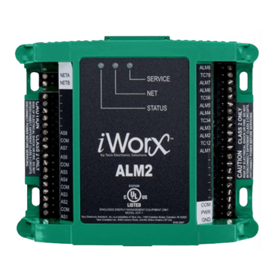
ALM2 Figure 6: Diagnostic LEDs Status Network Service Troubleshooting Tips The following table provides tips on resolving common issues. Problem Solution Controller is not running and Status No power to controller. Verify the voltage on the controller’s power connector (24 LED is not illuminated. - Page 19 ALM2 Getting Help Components within an iWorX® controller, sensor, or power supply cannot be field repaired. If there is a problem with a unit, follow the steps below before contacting your local TES representative or TES technical service. 1.Make sure controllers, sensors, and power supplies are connected and communicating to desired devices.
- Page 20 Taco Electronic Solutions, Inc. is a subsidiary of Taco, Inc. Visit our web site at: http://www.taco-hvac.com Printed in the USA iWorX® and iView® are registered trademarks of Taco Electronic Solutions, Inc. © 2010 Taco Electronic Solutions, Inc. LON, LONWORKS, & LONMARK are trademarks of Echelon Corporation...
Need help?
Do you have a question about the ALM2 and is the answer not in the manual?
Questions and answers