Table of Contents
Advertisement
Advertisement
Table of Contents

Related Manuals for BioNote Vcheck M10

Summary of Contents for BioNote Vcheck M10
- Page 1 FOR VETERINARY USE ONLY USER MANUAL...
- Page 2 Gyeonggi-do, 16690, Republic of Korea Manufacturing site 74, Osongsaengmyeong 4-ro, Osong-eup, Heungdeok-gu, Cheongju-si, Chungcheongbuk-do, 28161, Republic of Korea Tel: +82-31-300-0400 l Fax: +82-31-300-0499 www.sdbiosensor.com Distributed by 22, Samsung 1-ro 4-gil, Hwaseong-si, Gyeonggi-do, 18449, Republic of Korea Tel: +82-31-211-0516 l Fax: +82-31-8003-0618 www.bionote.co.kr...
- Page 3 Thank you for purchasing Vcheck M10. This user manual contains all information about the analyzer. Please carefully read this user manual and the instructions included in each test cartridge package before using the analyzer. In addition, please familiarize yourself with the necessary preparation and the procedures.
-
Page 4: Table Of Contents
3. Precautions 4. Warranty and Free Warranty Period Service Policy Overview CHAPTER 1. Intended Use 2. Product Overview 3. Components of Vcheck M10 4. Software GUI Description 5. Components 6. Specifications 7. Unpacking 8. Precautions Before Measurement Log On and Setting CHAPTER 1. - Page 5 Run Test Mode CHAPTER 1. Run Test 2. Result 3. Review CHAPTER 1. QC Test Cleaning and Maintenance CHAPTER 1. Analyzer Cleaning 2. Maintenance and Transportation Warning/Info/Error Messages CHAPTER 1. Warning Messages 2. Info Messages 3. Error Messages...
-
Page 6: General Information
CHAPTER 1 General Information 1. Main Menu Structure Login Test Review Settings Module Result Select General User Network Select List Patient QC Mode Summary Date/Time Login HIS/LIS Scan Select Sample Patient Amplification Laguage Add New Scan Scan Cartridge Sample Details Brigthness Edit Scan... -
Page 7: Symbols And Abbreviations
2. Symbols and Abbreviations The symbols and abbreviations presented below are stated in the user manual, labels, and external packages of Vcheck M10 System. Symbols Electrical Symbols on analyzer Symbols Description Indicates the ON position of the main power switch. - Page 8 Symbols Symbols Description Manufacturer Consult instructions for use Reference number Date of manufacture Indicates the date of manufacture Serial number Note Indicates that the analyzer is fragile, and must therefore be handled with care Fulfills the requirements of Electro Magnetic Compatibility Directive 2014/30/EU, Low Voltage Directive 2014/35/EU Indicates to keep the analyzer dry that you should keep the analyzer dry EU Representative...
-
Page 9: Precautions
7. Do not apply other products manufactured by the third party. 8. Before use, check the latest software with your dealer or BIONOTE. Then, start your updating. 9. It must be installed where the power supply and power switch are easily accessible, and easily disconnectable. -
Page 10: Warranty And Free Warranty Period Service Policy
• Nitrile latex gloves are recommended when handling specimens. 4. Warranty and Free Warranty Period Service Policy 1. The free warranty period of Vcheck M10 System is 2 years from the date of product installation. In the case of consumable parts, a separate warranty period is not provided. -
Page 11: Overview
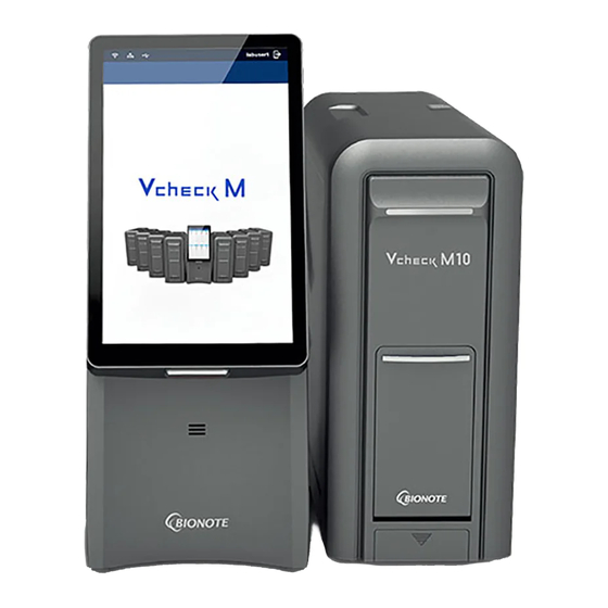
BIONOTE Vcheck M cartridge. This Vcheck M10 analyzer consists of the Vcheck M10 Module and the Vcheck M10 Console. The entire PCR process is carried out inside the Module, and the Console controls the process and shows the results. -
Page 12: Components Of Vcheck M10
3. Components of Vcheck M10 1) Vcheck M10 Console Front Side Back Item Name Description Displaying test screen and interacting with the graphic user Color TFT LCD screen interface. Barcode reader Used for scanning specimen IDs and cartridges barcodes. Speaker Audio output location. - Page 13 2) Vcheck M10 Module Front Side Back Status notification LED LED for indicating Module status. Insert or remove the cartridge from the chamber inside the Door door. Repair Cover Cover for manual rotation of the rotating motor. Cover for replacing the fan filter mounted on the vent that Fan Filter Cover discharges heat to the outside.
-
Page 14: Software Gui Description
4. Software GUI Description 1 2 3 Item Name Description Indicate the status of wired LAN connection Indicate the status of USB connection Indication alarm recommending calibration Home Move to the Home screen Setting User setting Review Check accumulated results User Indicate user’s name Log-Out... -
Page 15: Components
5. Components 1) Vcheck M10 Console Item Appearance Description Connect D-sub between D-sub cable console and module AC power cable Connect AC power of console 2) Vcheck M10 Module Item Appearance Description Connect AC power/ Gender D-sub between modules Terminate AC power of module... -
Page 16: Specifications
These vents must not be blocked when installing the analyzer. Avoid placing the analyzer in direct sunlight. Inspect for any obvious signs of damage. Report any damages immediately to BIONOTE. Allow the analyzer to equilibrate to room temperature at least 30 minutes before operating. -
Page 17: Precautions Before Measurement
To perform a test on the Vcheck M10 system, place the system on a flat surface. Do not use the Vcheck M10 system near strong sources of electromagnetic radiation, because the strong electromagnetic fields may impair the function of the analyzer. -
Page 18: Log On And Setting
Connect the supplied communication cable (D-sub cable) at the back of the Vcheck M10 Console and Vcheck M10 Module to link them together. • Connect the supplied AC power cable to the Vcheck M10 Console and the Vcheck M10 Module respectively. •... - Page 19 2-1) Installing additional M10 Modules • Connect the M10 Modules using the bracket and screws supplied with M10 Module. Bracket • Connect the supplied gender at the back of the M10 Module (#1) and M10 Module (#2) to link them together. Gender...
- Page 20 2-2) Installing additional M10 Modules • Connect multiple modules using bracket and side bracket. Bracket Side Bracket...
-
Page 21: Analyzer Login
1.2 Analyzer LogIn • To start, login after power on. • Click the input box to create a virtual keyboard. • Login ID is admin and password is 1111. (Change the password of "admin" account at initial log on for further security.) •... - Page 22 • If you enter an incorrect ID or password, the icon may turn red and the warning pop-up may appear. • If you log in successfully, an installation will proceed automatically. • The installed modules are recognized in the order in which they are connected.
-
Page 23: Analyzer Status Light
1.3 Analyzer Status Light Yellow State Indication Not connected Installing LED sign Blue Green State Indication Connected Running LED sign... - Page 24 When the connection is completed, you can use the analyzer. • Re-installation is required for following situations. - When the number of M10 Module has changed. - When the position of M10 Module has changed. - If the number of connected M10 Module and the number of M10 Module recognized on UI are different.
-
Page 25: Analyzer Settings
1.4 Analyzer Settings • For the cyber security, the admin password must be changed at initial login. • Important functions of the system, including updating of the system, can be changed and applied only by admin account. (After resetting the admin's password, it is very recommended to be noted.) •... - Page 26 1. Select on the main menu screen to enter the Settings menu. 2. Settings menu consists of General, User, and Network.
- Page 27 3. In General category, you can set Date/Time, Language, Brightness/Volume, process updates, and Module installation. Menu Description You can set the year, month, day, hour, and minute. If you click the input box, a Date/Time number keyboard will appear. Language English is the default.
- Page 28 4. In User category, Operator ID can be registered, edited, and deleted. 5. If you click the input box, a keyboard will appear. In User category, the password is same as the Password when you logged in. 6. In User category, you can add an Operator ID by clicking the button.
- Page 29 • Enter the ID and password to be added. Click the button. If the password is incorrect, the 'Please check password' will appear. •...
- Page 30 • If the same ID exists, 'User ID is already used' will appear. • Make sure that PW consists of 8 to 15 characters including numbers and lowercase letters. 7. To edit the Operator ID, select the ID to be modified. Press button on the Edit screen.
- Page 31 8. To delete the Operator ID, select the ID to be deleted and press button. Then press button on Delete screen. 9. In Network category, you can set the Network of HIS/LIS and analyzer. • Set the network IP, Netmask, Gateway, Port of the M10 Console. Apply it through the Save button.
- Page 32 • This is the UI for TCP/IP, DHCP, and Additional to use extensions. This is not currently used. • Protocol has Off/HL7/LAW methods. Select the desired communication method among them. After that, click the button to apply the desired results. (If Off is selected, the result Save data for the patient will not be transmitted even if the Auto send function is activated.)
- Page 33 • Security can be set to Off or SSL. If SSL(Off) is selected, it operates according to the protocol Off/HL7/LAW set above. If SSL(Off) is selected, a pop-up window will appear. • When you click Import, the *.crt file in the USB memory will install the certificate into the M10 Console.
- Page 34 • Auto Send sets whether to send the result data after testing the patient to the server, applying the set protocol and security. When set to On, the setting is activated. (For example, if protocol HL7 setting and Security Off are set, the patient's test result is transmitted to the server without security through HL7 communication.)
-
Page 35: Run Test Mode
CHAPTER 4 Run Test Mode Check the followings before performing assays. • Is the power cable connected to the analyzer? • Is the set date and time on the analyzer correct? • Have you checked the analyzer settings? 1. Run Test 1. - Page 36 2. Select the M10 Module to drive press to move to the next step. (Only M10 Modules in Completed or Available status can be operated.) 3. Scan the barcode of the sample or manually type the sample ID. If the input is successful, it automatically moves to the next step.
- Page 37 4. Scan the barcode of the cartridge to be used. If the input is successful, it automatically moves to the next step. 5. Inject the specimens into the test cartridge. Then touch the screen or wait 9 seconds. Place the cartridge in the M10 Module immediately. Close the M10 Module door manually. (Refer to Procedure in the assay specific Vcheck M Cartridge instructions for further details.)
- Page 38 6. If the cartridge is inserted into the M10 Module, the next screen will be displayed. Select to proceed, or select to restart. Reset 7. It automatically checks the surface temperature of the cartridge and the proper operation of the optical module. After that, the test proceeds.
- Page 39 8. When the assay is completed, the M10 Module Door opens automatically. Once the operation is completed, remove the used cartridge immediately. Dispose of as biohazardous waste and dispose of immediately.
-
Page 40: Result
2. Result In Result, you can check the test results. 1. You can check the summary of a result in the Summary tab. Pathogen IC Valid 2. You can check the target amplification graph for each item in the Amplification tab. Result Result Result... -
Page 41: Review
3. You can check detailed result information in the Details tab. 3. Review You can check the accumulated test results in Review . You can check the detailed results of each test. Pathogen IC Valid Babesia gibsoni 22.94 Ct Babesia canis 24.94 Ct... -
Page 42: Qc Test
CHAPTER 5 Check the following before performing measurements. • Is the power cable connected to the analyzer? • Is the set date and time on the analyzer correct? • Have you checked the analyzer settings? • Is the QC control solution ready? 1. - Page 43 3. The barcode of the specified QC Solution should be scanned. If the barcode of the QC to be tested is recognized, it automatically moves to the next stage. If you scan the QC barcode provided by the BIONOTE, the QC check box is automatically checked.
- Page 44 4. The next step will be proceeded the same as the Run Test. 5. If the test is completed, the result will be recorded in Review. If you click the QC filter, you can review only QC results.
-
Page 45: Cleaning And Maintenance
Always turn off the analyzer and remove the power cable before cleaning. 2. Maintenance and Transportation If there is any problem on the Vcheck M10 system, the Console automatically shows what went wrong for each time the system is powered on. •... -
Page 46: Warning/Info/Error Messages
CHAPTER 7 Warning/Info/Error Messages 1. Warning Messages Indication Warning Description Warning: Not connected USB USB is not connected to analyzer. Solution Confirm that USB is correctly inserted into analyzer. Warning: Wrong ID or Password Wrong ID or password is input. Solution Input the correct ID or password. -
Page 47: Info Messages
Warning: Please reject cartridge. Please remove any cartridges or stuck material inside the M10 Module before proceeding the test. Solution After removing the cartridge or stuck material inside the M10 Module, click the OK button.. Warning: Not registered USB. The USB memory stick inserted into the M10 Console is not registered. - Page 48 Information: Please scan patient barcode. Solution As this error occurs when scanning the Vcheck M Cartridge, please scan the patient barcode. Information: Please scan sample barcode. Solution As this error occurs when scanning the Vcheck M Cartridge, please scan the sample barcode. Information: Saved to USB memory Information: Have no *.crt file in USB memory Solution...
-
Page 49: Error Messages
3. Error Messages Indication Error Description Error: Used Device Test cartridge is damaged or inaccurately inserted into the analyzer. Solution Discard the failed test cartridge and re-test with a new test cartridge and new specimen. Error: Expired Device Expired test cartridge is used. Solution Re-run the test with a new test cartridge that has not expired. - Page 50 Error: Operation module Piston Encoder Error While operating the cartridge in the M10 Module there was a problem with the operation of the vertical piston motor. Solution If error occurs, the tests will be canceled and the door of M10 Module will be opened. Proceed the test with a new cartridge.
- Page 51 Error: Not Supported Device Solution Use the cartridge barcode provided by BIONOTE. Error: Optic Detail Error. Error in M10 Optical Measurement Module. Solution Turn off the power of M10 Console and M10 Module and check if the cable and gender are properly connected.
Need help?
Do you have a question about the Vcheck M10 and is the answer not in the manual?
Questions and answers