Table of Contents
Advertisement
Quick Links
Advertisement
Table of Contents

Summary of Contents for Schloder SESD 200
- Page 1 OPERATION MANUAL ESD - GENERATOR SESD 200...
- Page 2 VDE 0140. People using cardiac pacemakers should be excluded from the test area. Before using the generator please read this manual and also the warnings to the safety points under item 1 User manual SESD 200 page 2...
-
Page 3: Table Of Contents
..............15 ECOMMENDATION FOR THE SET UP OF A TESTING CORNER TECHNICAL DATA..........................16 9.1............................16 ENERATOR 9.2. - / C .......................16 ONTACT DISCHARGE 9.3...........................16 OWER SUPPLY SCOPE OF DELIVERY ........................16 BLOCK SCHEMATIC DIAGRAM ....................17 User manual SESD 200 page 3... -
Page 4: Safety Regulations
1.1. Warnings The test generator SESD 200 creates high voltage up to 16.500 Volts. The energy of this high voltages is limited, but injury might be incurred if the probe tip is touched. The handling of the generator is only allowed to experienced and instructed persons according to DIN 570105 / VDE 0105 part 1. -
Page 5: Introduction
Introduction The test generator SESD 200 simulates "Electrostatic Discharge" as defined in the standard IEC /EN 61000-4-2. The standard shows two test modes: a) Air discharge The discharge electrode with the domed point should first be connected to the SESD. The high voltage discharge of the generator is into an air gap. -
Page 6: Unit Functions
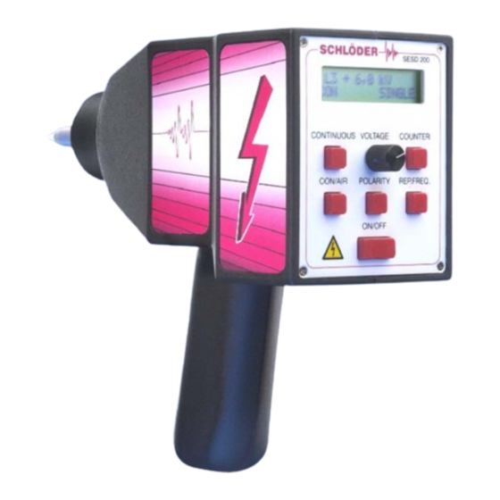
ON / OFF - switch Potentiometer output voltage adjust and special function Polarity of the pulse, positive and negative Mode CON / AIR - contact discharge or air discharge Repetition frequency Counter pre-selectable Continuous discharge LCD - Display User manual SESD 200 page 6... -
Page 7: Case
[9] Trigger key Drawing 3 4.3. Power supply Drawing 4 [14] POWER - LED (green) [15] CHARGE - LED (yellow / red) [16] Function select switch for line using or charging [17] Connector to ESD generator User manual SESD 200 page 7... -
Page 8: Description Of Function
Referring to the standard tests the electrostatic discharges have to be tested in positive (+) and negative (-) polarity. The display shows the chosen polarity on the left hand of the voltage value, "+" or "-". User manual SESD 200 page 8... -
Page 9: Mode Con / Air
By pressing the key a number of times the following repetition frequencies (shown on the right hand in the lower line of the display) can be chosen. Air discharge: SINGLE or REP (single pulse or repeated). Contact discharge: SINGLE, 1 Hz, 2 Hz, 5 Hz, 10 Hz or 20 Hz. User manual SESD 200 page 9... -
Page 10: Adjust Pre-Select Counter
The discharge return cable has to be connected to the ground connector [10]. The other end has to be connected to ground, either to the ground plane of the test bay or directly to the EUT. User manual SESD 200 page 10... -
Page 11: Discharge Electrodes For Con / Air
5.12. Connector power supply The generator is connected to the power supply via the socket [12]. The SESD 200 can be used either independently, using the built in batteries or while connected to the mains supply. The default usage of the generator is in the accumulator-supply. -
Page 12: Power Supply
6.4. CHARGE - LED The ESD generator SESD 200 works with a Lithium-Ionen accumulator which has a capacity of 1,3 Ah. This type of accumulator needs a special charging electronic. A microprocessor controlled IC creates necessary constant current and constant voltage. -
Page 13: Calibration
IEC 61000-4-2 / EN 61000-4-2. The most important parameters like rise time and pulse width are defined with a tolerance of ± 30%. Therefore w e recommend a calibration every three years !! User manual SESD 200 page 13... -
Page 14: Esd Test Field
Horizontal Coupling Plate (160 x 80 cm) typical position for indirect discharge to the horizontal coupling plate (HCP) Resistor’s 470 kOhm Ground plane (earth reference) Wooden table (h = 80 cm) ESD power supply User manual SESD 200 page 14... -
Page 15: Recommendation For The Set-Up Of A Testing Corner
• The metal plates must be connected with low impedance, either by welding or with copper tape. The ground plate on the table is connected via 470 kΩ-resistors with the ground plane. User manual SESD 200 page 15... -
Page 16: Technical Data
• Power supply with battery charger • Cable from the power supply to the ESD generator • Discharge return cable 2 m long • Discharge electrodes for Contact discharge • Discharge electrodes for Air discharge • Operation manual User manual SESD 200 page 16... -
Page 17: Block Schematic Diagram
S c h l ö d e r G m b H EMV-Systeme & Komponenten Hauptstrasse 71 D - 75210 Keltern-Weiler Germany Tel. : +49 (0)7236 / 9396 - 0 : +49 (0)7236 / 9396 - 90 e-mail : info@schloeder-emv.de : www.schloeder-emv.de User manual SESD 200 page 17...
Need help?
Do you have a question about the SESD 200 and is the answer not in the manual?
Questions and answers