
Related Manuals for Albalá Ingenieros GPD2000C01

Summary of Contents for Albalá Ingenieros GPD2000C01
- Page 1 GPD2000C01 1 INPUT TO 4 OUTPUTS GNSS ANTENNA SIGNAL DISTRIBUTION AMPLIFIER Version 1.0 Albalá Ingenieros, S.A. 13 January 2022 - © Albalá Ingenieros S.A. - All rights reserved Medea, 4 - 28037 Madrid - Spain...
- Page 2 GPD2000C01...
-
Page 3: Table Of Contents
4. OPERATION ........................15 4.1. Front panel description ......................15 4.2. Functional description ....................... 16 4.3. Module remote control and supervision ................18 4.3.1. Details of the GPD2000C01 registers ................19 5. GLOSSARY ........................21 6. REGULATIONS ........................23 7. VERSIONS ......................... 25... - Page 4 GPD2000C01...
-
Page 5: Description
SNMP management and the ability to record events in a file including date and time information for further analysis. The GPD2000C01 is a TL2000 terminal line module and can be housed in a two rack unit (2 RU) UR2000 mounting frame. -
Page 6: Features
GPD2000C01 1.2. Features • The GPD2000C01 module is a GNSS signal distributor from one input to four outputs. • Provides a 20 dB gain between the input and any of the outputs in order to compensate the attenuation introduced by the cable through which the signal is received from the antenna. -
Page 7: Block Diagram
Albalá Ingenieros | Manual GPD2000C01 1.3. Block diagram... - Page 8 Albalá Ingenieros | Manual GPD2000C01 GPD2000C01...
-
Page 9: Specifications
Albalá Ingenieros | Manual GPD2000C01 2. SPECIFICATIONS Antenna conection for GPS signal Connector SMA female Impedance 50 Ω Standing wave ratio (VWSR) Provided antenna voltage 3 V or 5 V ± 5 % user selectable Provided antenna current 80 mA max. - Page 10 Albalá Ingenieros | Manual GPD2000C01 GPD2000C01...
-
Page 11: Installation
• The GPD2000C01 module and the mounting frame should always be installed, maintained, operated and removed by personnel with sufficient technical qualifications. The equipment should never be placed in damp areas, near splashing liquid, or in explosive or corrosive atmospheres. -
Page 12: Environmental Considerations
1 - Remove the blank panel covering the front of the empty slot chosen for installing the GPD2000C01 in the mounting frame. 2 - Insert the GPD2000C01 module into the front of the mounting frame. The edges of the card slide into two plastic guides inside the mounting frame. -
Page 13: Interconnection
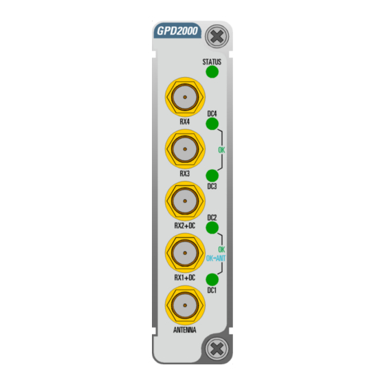
Albalá Ingenieros | Manual GPD2000C01 3.5. Interconnection The arrangement of the front panel connectors of the GPD2000C01 module is shown in the following figure. Front panel of the GPD2000C01 The SMA connector identified on the front of the module as ANTENNA is the GNSS signal input and also the voltage supply output. - Page 14 Albalá Ingenieros | Manual GPD2000C01 GPD2000C01...
-
Page 15: Operation
Albalá Ingenieros | Manual GPD2000C01 4. OPERATION This section describes the significance of the front panel indicators of the GPD2000C01 module and their remote control and monitoring ability. 4.1. Front panel description The appearance of the front panel and the elements it contains are shown in the following illustration. -
Page 16: Functional Description
GNSS signal. The voltage used to power the antenna can come from an internal power supply to the GPD2000C01 module or from one of the GNSS receivers the GPD2000C01 has connected to the outputs labeled RX1+DC and RX2+DC. The power... - Page 17 Albalá Ingenieros | Manual GPD2000C01...
-
Page 18: Module Remote Control And Supervision
Albalá Ingenieros | Manual GPD2000C01 4.3. Module remote control and supervision The GPD2000C01 can optionally be remotely controlled/supervised. In order to perform remote configuration and supervision of the module an optional TL2000 family remote communications controller must be installed in the mounting frame. -
Page 19: Details Of The Gpd2000C01 Registers
GNSS receivers to which the signal is distributed. 4.3.1. Details of the GPD2000C01 registers The GPD2000C01 module provides control and status registers that can be read and written by means of specific commands described in the communication control module user manuals. - Page 20 Albalá Ingenieros | Manual GPD2000C01 VCC_GNSS_LOW 0x02 0xFF VCC low threshold = x/45 V ICC_ANTENNA_LOW 0x03 0xFF ICC low threshold = x/3.4 mA ICC_ANTENNA_HIGH 0x04 0xFF ICC high threshold = x/3.4 mA STATUS Name snmp trap Description VCC_GNSS1_FAIL 0x01 0x01...
-
Page 21: Glossary
Albalá Ingenieros | Manual GPD2000C01 5. GLOSSARY GNSS Global Navigation Satellite System. Satellite navigation system with global coverage. SubMiniature version A connector. - Page 22 Albalá Ingenieros | Manual GPD2000C01 GPD2000C01...
-
Page 23: Regulations
Albalá Ingenieros | Manual GPD2000C01 6. REGULATIONS... - Page 24 Albalá Ingenieros | Manual GPD2000C01 GPD2000C01...
-
Page 25: Versions
Albalá Ingenieros | Manual GPD2000C01 7. VERSIONS Ver. Date Description 26-05-2021 Preliminary Version 13-01-2022 First version... - Page 26 Albalá Ingenieros, S.A. Medea, 4 - 28037 Madrid Spain +34 913274453 www.albalaing.com info@albalaing.com...
Need help?
Do you have a question about the GPD2000C01 and is the answer not in the manual?
Questions and answers