Panasonic SL-PR300 Service Manual
Compact disk recorder
Hide thumbs
Also See for SL-PR300:
- Operating instructions manual (50 pages) ,
- Operating instructions manual (52 pages)

Subscribe to Our Youtube Channel
Related Manuals for Panasonic SL-PR300


Summary of Contents for Panasonic SL-PR300
- Page 1 ORDER No.AD0109130C1 Compact Disk Recorder SL-PR300 Mechanism unit:FMU-ZC4-1M (CD Changer),EMU-R7-1M (CD-R) Colour (S)....Silver Type Area PP....U.S.A. and Canada. SPECIFICATIONS Specifications...
- Page 2 CD Player Section System Compact disc digital audio system Pitch control ±12% Signal-to noise ratio 97 dB (1 kHz) Dynamic range 93 dB (1 kHz) Frequency response 20 Hz - 20 kHz (±1 dB) Wow and flutter Less than measurable limit Total harmonic distortion 0.0063 % (1kHz) CDR Section System...
- Page 3 Unauthorized copying and distribution is a violation of law. 1. Accessories - Remote control batteries....2pcs. [R6/LR6 (AA, UM-3) ] Note:These are available on sales route. - Stereo phono cables....2pc. (RJL2P004B08A) - Remote control transmitter....1pc. (RAK-PR300) 2. Safety Precaution (This “Safety Precaution” is applied only in U.S.A..) 1.
- Page 4 is evident. 4. After servicing, be sure to restore the lead dress, insulation barriers, insulation papers, shields etc.. 5. Before returning the serviced equipment to the customer, be sure to make the following insulation resistance test to prevent the customer from being exposed to a shock hazard. 2.1.
- Page 5 3. Precaution of Laser Diode Caution: This unit utilizes a class 1 laser. Invisible laser radiation is emitted from the optical pickup lens when the unit is turn on: 1. Do not look directly into the pickup lens. 2. Do not use optical instruments to look at pickup lens. 3.
- Page 6 user but they do not allow such recordings to be used for any other purpose without permission from the rightful owner of the copyrights. Notes - If digital recording of a first generation digital copy is attempted, “SCMS PROTECT” is shown in the information display, and the recording operation is canceled.
- Page 7 Notes - The unit can playback audio data recorded on CD-G, CD-EXTRA and CD-Text discs as well, however the text information of CD- Text discs cannot be displayed. - If a CD-R or CD-RW has been recorded using a personal computer, playback is only possible if the disc is recorded in the CD-Digital Audio format.
- Page 8 6.1.3. Handling the optical pickup 1. In order to maintain quality during transport and before installation, both sides of the laser diode on the replacement optical pickup are shorted. After replacement, return the shorted parts to their original condition. (Refer to the text.) 2.
- Page 9 3. Handle the flexible cable carefully as it may break when subjected to strong force. 4. It is not possible to adjust the semi-fixed resistor that adjusts the laser power. Do not turn it 7. Precautions for Service [Handling of Traverse Unit and Laser Pickup] 1.
- Page 10 [Destruction of Traverse Unit and Laser Pickup by Static Electricity] Laser diodes are easily destroyed by static electricity charged on clothing or the human body. Before repairing peripheral elements of the traverse unit or pickup, be sure to take the following electrostatic protection: 1.
- Page 11 8. How to check the abnormalities of the CD-R/RW mechanism unit and repair them. In this model, the entire CD-R/RW mechanism unit must be replaced. When the source of the problem appears to be in the CD-R/RW mechanism unit, check it using the following procedure and replace it.
- Page 12 9. Operation Checks and Component Replacement Procedures...
- Page 25 10. All Lighting FL Display and Reducing Time Operation of Clock The clock display comes to advance during one minute a second in actual time when changing to this method. Because other operation can do the normal operation, uses for the confirmation of the operation of the timer function etc..
- Page 26 10.1. Preparation Please setting the present time when the time display has blinked “0:00”. 10.2. Setting method 1. “POWER ” key is pushed while pushing “REC/REC MUTE” key by the stand-by state. (Enter the “All Lighting FL Display” mode.) 2. “POWER ”...
- Page 27 2. When the blinking display of the disc distinction ends, “MENU” key is pushed. *The menu display changes if “MULTI JOG” knob of the main body is turned. (Refer to Fig. 12-1.) Fig. 12-1 Note: The execution of the each item is completed or either “CANCEL” key, “CD-RW STOP” key or “MENU”...
- Page 28 Fig. 12-2 Notes: 1. If the running operation is started without the disc installed, the message “000CD 1ACOPY” will be displayed. 2. The running operation is immediately stopped by pressing any of effective input by key, the remote controller, DCS operation. When running operation is interrupted by the “STOP”...
- Page 29 12.3.1. Setting method 1. “Service menu” is made to be displayed on the FL display referring to the abovementioned. 2. “READ VERSION” is made to turn “MULTI JOG” knob, and to be displayed on the FL display. 3. Version number is displayed in FL display for five seconds when “SET”...
- Page 31 14. Description of major ICs...
- Page 42 15. Schematic Diagram Notes This schematic diagram may be modified at any time with the development of new technology. Notes: - S71 : POWER switch. - S702 : STOP switch. (3-CD changer) - S703 : PLAY MODE switch.
- Page 43 - S704 : PAUSE switch. (3-CD changer) - S705 : CD EDIT switch. - S706 : PLAY switch. (3-CD changer) - S707 : CANCEL switch. - S708 : SET switch. - S710 : CD REC switch. - S721 : STOP switch.
- Page 44 with the chassis taken as standard. Therefore, there may exist some errors in the voltage values, depending on the internalimpedance of the DC circuit tester. No mark: CD STOP ( ): CD play [1kHz, L+R, 0dB] Important safety notice: Components identified by mark have special characteristics important for safety.
- Page 45 16. Schematic Diagram 17. Printed Circuit Board 18. Block Diagram 19. Wiring Connection Diagram 20. Replacement Parts List Notes: *Important safety notice: Components identified by mark have special characteristics important for safety. Funrthermore, special parts which have purposes of fire-retardant (resistors), high-quality sound (capacitors), low-noise (resistors), etc.
- Page 46 Ref. No. Part No. Part Name & Description Remarks LE10256-001A FRONT PANEL VGB0298 PANASONIC BADGE LE30956-001A WINDOW SCREEN QYSBSGY3008M SCREW LE30958-001A INDICATOR RKW0273-N REMOTE LENS LE20592-001A P.BUTTON LE30957-001A INDICATOR LE10248-003A P.BUTTON LE20528-004A P.BUTTON LE30894-002A JOG KNOB LV40061-004A KNOB LE40791-001A H.P.BRACKET...
- Page 47 Ref. No. Part No. Part Name & Description Remarks QMPD100-200K POWER SUPPLY CORD QHS4077-108 S.R BUSHING LV20581-001A CHASSIS UNIT RF500TB12560 MOTOR VKS5548-001 MOTOR PULLEY QYSPSP2603Z SCREW LV31586-001A SELECT GEAR LV41427-001A SELECT SPRING LV20588-001A GEAR BASE UNIT QYSDST2606Z SCREW LV41431-001A BELT LV20586-003A SUB CHAS.
- Page 48 LV42668-001A CAUTION SHEET...
- Page 49 Ref. No. Part No. Part Name & Description Remarks RQA0149-1 WARRANTY CARD RQF4066 WARRANTY CARD RQCB0831 SVC CENTER LIST B100-21 NRS181J0R0NY 1/8W 0 B123-46 NRS181J0R0NY 1/8W 0 B147-49 NRSA63J-0R0X 1/16W 0 B151-55 NRSA63J-0R0X 1/16W 0 B157,58 NRSA63J-0R0X 1/16W 0 B159 NRS181J0R0NY 1/8W 0 B160,61...
- Page 50 Ref. No. Part No. Part Name & Description Remarks C341,42 QCZ0205-155Z 25V 1.5U C351 NCF31CZ-104X 16V 0.1U C352 QETN1CM-107Z 16V 100U C353 NCF31CZ-104X 16V 0.1U C354 NCB21HK-104X 50V 0.1U C355 NCS31HJ-101X 50V 100P C356 QETN1EM-476Z 25V 47U C357 NCS31HJ-151X 50V 150P C358 NCB31HK-221X 50V 220P...
- Page 51 Ref. No. Part No. Part Name & Description Remarks C663,64 NCB31HK-223X 50V 0.022U C665 NCB31AK-154X 10V 0.15U C667 NCB31AK-474X 10V 0.47U C669 QERF1AM-227Z 10V 220U C673 QERF1AM-227Z 10V 220U C676,77 NCB31CK-104X 16V 0.1U C679 QERF1AM-107Z 10V 100U C680 NCB31CK-104X 16V 0.1U C691,92 NCS31HJ-102X 50V 0.001U...
- Page 52 Ref. No. Part No. Part Name & Description Remarks C916 QETN1CM-477Z 16V 470U C917 QETM1EM-688 25V 6800U C918 QETN0JM-108Z 6.3V 1000U C921 QETM1EM-688 25V 6800U C922 QCF31HZ-103Z 50V 0.01U C923 QETN1HM-105Z 50V 1U C924 QETN0JM-108Z 6.3V 1000U C926,27 QCF31HZ-103Z 50V 0.01U C932 QETN1AM-477Z 10V 470U...
- Page 53 Ref. No. Part No. Part Name & Description Remarks CN71 QGF1205C1-11 CONNECTOR(11P) CN401 QGD2503F1-05 SOCKET(5P) CN501 QGF1205C1-19 CONNECTOR(19P) CN505 QGF1205C1-06 CONNECTOR(6P) CN541 QGF1205F1-19 CONNECTOR(19P) CN601 QGF1016C1-21 CONNECTOR(21P) CN606 QGF1016F3-08 CONNECTOR(8P) CN608 QGF1016F3-04 CONNECTOR(4P) CN610 QGB1214J108S CONNECTOR(8P) CN615 QGF1016C1-19 CONNECTOR(19P) CN616 QGF1016C1-08 CONNECTOR(8P) CN620...
- Page 54 Ref. No. Part No. Part Name & Description Remarks D971 1SR35-400AT5 DIODE D972 UDZS5.6B-X DIODE D981,82 DA114-X DIODE D991,92 DA114-X DIODE D1301 DA114-X DIODE D2301 DA114-X DIODE DI721 QLF0088-001 FL DISPLAY TUBE FW71 QUM02513DGZ3 PARA RIBON WIRE FW91 QUM02912DGZ3 PARA RIBON WIRE IC71 GP1U281X IC201...
- Page 55 Ref. No. Part No. Part Name & Description Remarks K311 NQR0227-004X FERRITE BEADS K351 NQR0227-004X FERRITE BEADS K358 NQR0227-004X FERRITE BEADS K381-83 NRSA63J-0R0X MG RESISTOR,1/4W 0 K384,85 NQR0227-004X FERRITE BEADS K387 NQR0227-004X FERRITE BEADS K391-93 NQR0227-004X FERRITE BEADS K501 NQR0227-004X FERRITE BEADS K655 NQR0007-002X...
- Page 56 Ref. No. Part No. Part Name & Description Remarks Q1301 KRC103M-T TRANSISTOR Q1401 KTC3199/GL/T TRANSISTOR Q2301 KRC103M-T TRANSISTOR Q2401 KTC3199/GL/T TRANSISTOR R111 NRSA63J-223X 1/16W 22K R112,13 NRSA02F-223X 1/10W 22K R114 NRSA02F-222X 1/10W 2.2K R115 NRSA02F-152X 1/10W 1.5K R116 NRSA63J-473X 1/16W 47K R117 NRSA02F-152X 1/10W 1.5K...
- Page 57 Ref. No. Part No. Part Name & Description Remarks R275A NRSA63J-223X 1/16W 22K R276 NRSA63J-103X 1/16W 10K R277 NRSA63J-0R0X 1/16W 0 R277A NRSA63J-103X 1/16W 10K R278-80 NRSA63J-102X 1/16W 1K R281 NRSA63J-473X 1/16W 47K R281A NRSA63J-102X 1/16W 1K R282 NRSA02J-471X 1/4W 470 R283 NRSA63J-222X 1/16W 2.2K...
- Page 58 Ref. No. Part No. Part Name & Description Remarks R540 NRSA63J-473X 1/16W 47K R541 NRSA63J-223X 1/16W 22K R545 NRSA63J-223X 1/16W 22K R551 NRSA63J-472X 1/16W 4.7K R555,56 NRSA63J-473X 1/16W 47K R557 NRS181J-473X 1/8W 47K R558 NRSA63J-103X 1/16W 10K R561 NRSA02J-471X 1/4W 470 R562 NRSA02J-102X 1/4W 1K...
- Page 59 Ref. No. Part No. Part Name & Description Remarks R703 NRSA02J-122X 1/4W 1.2K R704 NRSA02J-182X 1/4W 1.8K R705 NRSA63J-272X 1/16W 2.7K R706 NRSA63J-332X 1/16W 3.3K R707 NRSA63J-562X 1/16W 5.6K R721,22 NRSA02J-102X 1/4W 1K R723 NRSA02J-122X 1/4W 1.2K R724 NRSA02J-182X 1/4W 1.8K R725 NRSA63J-272X 1/16W 2.7K...
- Page 60 Ref. No. Part No. Part Name & Description Remarks R883 NRSA02J-101X 1/4W 100 R901 QRZ9006-4R7X R902 NRSA02J-222X 1/4W 2.2K R903 NRSA02J-622X 1/4W 6.2K R904 NRSA02J-472X 1/4W 4.7K R905 QRZ9006-4R7X R906 NRSA02J-472X 1/4W 4.7K R908 NRSA02J-392X 1/4W 3.9K R911 NRSA02J-181X 1/4W 180 R921 NRSA02J-222X 1/4W 2.2K...
- Page 61 Ref. No. Part No. Part Name & Description Remarks R2403 NRSA63J-103X 1/16W 10K R2404 NRSA63J-823X 1/16W 82K R2501-03 NRSA02F-183X 1/10W 18K R2504 NRSA02F-222X 1/10W 2.2K R2505-07 NRSA63J-332X 1/16W 3.3K R2510 NRSA63F-162X 1/16W 1.6K R2511,12 NRSA63J-273X 1/16W 27K R5010 NRSA63J-272X 1/16W 2.7K QSW0683-001Z PUSH SWITCH S702-08...
- Page 63 22. Changer Mechanism Parts Location...
- Page 66 23. Packaging...
- Page 67 24. Schematic Diagram for printing with A4 size H010900000 TN/AM...
- Page 68 S722 S761 S704 S702 S724 B1228 SL-PR300(PP) POWER TRANSFORMER :These parts haven t been used on the circuit. POWER SW,MULTI JOG, (These parts are not mentioned in the Schematic diagram and the Replacement parts list .) HEADPHONE,FL, DETECTION SW P.C.B...
- Page 69 R291 R292 SW680 Q602 IC291 C652 R662 R668 C664 C651 C680 C617 C679 C679 R683 C676 D852 R682 IC601 R279 R614 C601 C661 C602 C625 C606 CN610 R605 SW690 SW690 SW691 SW692 CN610 SW692 SW691 C633 SL-PR300(PP) CD SERVO P.C.B.
- Page 70 UDZS36B-X 1SR35-400A-T5 R844 10/50 -34.7V -8.4V R943 C944 4.9V SLIN2- R941 10/50 D944 4.7K -36.5V 4.9V -36V -46.9V R942 Q941 2SB647/CD/-T C945 D945 UDZS7.5B-X 100/16 CN841 QGF1205C1-13 MULTI JOG CIRCUIT (CN801) on SEET 3/4 SHEET SL-PR300(PP) MAIN,POWER TRANSFORMER SCHEMATIC DIAGRAM...
- Page 71 220p K358 C513 R580 DITOUT R503 R502 100K EP501 QNZ0136-001Z D503 C359 0.022 C370 IC311 TC74HC00AF-X R305 R311 R312 C710 3.3K 3.3K C311 EP701 QNZ0136-001Z CN711 QGF1205F1-11 J353 QNN0347-001 POWER SW CIRCUIT(CN71) on SEET 3/4 SHEET SL-PR300(PP) MAIN SCHEMATIC DIAGRAM...
-
Page 72: Table Of Contents
IC621 5.6K BA15218F-XE S725 C1201 C6210 0.047 100P K6202 QSW0683-001Z QQR1272-001 S726 C2201 K2201 DI721 100P W1220 QSW0683-001Z R2204 K1201 J6201 5.6K QNS0031-001 S710 R2205 R2206 QSW0683-001Z R2201 -8.6V C6203 C6204 W1200 100/16 SHEET SL-PR300(PP) POWER SW,MULTI JOG,HEADPHONE,FL SCHEMATIC DIAGRAM... - Page 73 D667 QAR0123-001 MA152WA-X D801 C651 C652 1SR154-400-X C822 C821 220/10 1/10 R691 R695 OUTL OUT_L C691 C693 0.001 0.0027 C692 C694 0.001 0.0027 OUTR OUT_R R808 R692 R696 R809A 1.5k R805 5.6k SHEET SL-PR300(PP) CD SERVO, DETECTION SW SCHEMATIC DIAGRAM...
- Page 74 1 ..19 1 . . 7 CN651 2 ..18 2 . . 8 CN608 CN541 FL P.C.B. MULTI JOG P.C.B. CD SERVO P.C.B. CN801 CN601 CN610 1 .
-
Page 75: On Seet 4/4
MAIN CIRCUIT R1510 8.5V 1.6K R1305 C1506 R181 3300P IC881 NJM4580M-X C1303 8.5V R1304 R1313 1/50 6.8K 5.9V Q1301 KTC103M-T C1301 R1301 4.7V 1/50 D1301 1.5K C2506 3CDINL R281 3300P R1306 R1307 R1302 -8.6V R1312 R2510 R1303 1.6K C1322 220K 0.47/50 R881 C1312... - Page 76 D943 D941 C943 UDZS36B-X 1SR35-400A-T5 R844 10/50 -34.7V -8.4V R943 C944 R941 4.9V SLIN2- D944 10/50 4.7K -36.5V 4.9V -36V -46.9V R942 Q941 2SB647/CD/-T C945 D945 UDZS7.5B-X 100/16 CN841 QGF1205C1-13 JOG CIRCUIT EET 3/4 SHEET SL-PR300(PP) MAIN,POWER TRANSFORMER SCHEMATIC DIAGRAM...
- Page 77 MAIN CIRCUIT CN723 CN722 QGF1016C1-08 QGF1016C1-23 R365 Q301 KRC103M-T 1.8V K391 K392 R371 R383 K393 K387 K384 R1501 R1503 -1.8V (-1.8V) 0V (4.9V) 4.9V DATA R369 1.8V 4.4V LRCK R370 4.4V 1.7V R1504 XBCK R368 R1502 C1502 2.2K 4.4V 180P R384 8.5V C1505...
- Page 78 FLCS- R565 (CN541) R556 FLCLK R564 on SEET 3/4 FLDAT R561 R533 R540 R501 R5010 2.7K C513 R580 R503 R502 100K EP501 QNZ0136-001Z D503 C710 EP701 QNZ0136-001Z CN711 QGF1205F1-11 POWER SW CIRCUIT(CN71) on SEET 3/4 SHEET SL-PR300(PP) MAIN SCHEMATIC DIAGRAM...
-
Page 79: To Amain Circuit (Cn711) On Seet
MULTI JOG CIRCUIT POWER SW JS721 FL CIR QSW0446-001 CIRCUIT S702 R1404 QSW0683-001Z 8.5V R1401 S703 C1401 QSW0683-001Z 4.7/50 IC722 S704 BA15218F-XE QSW0683-001Z R1402 QSW0683-001Z IC71 S705 C2401 GP1U281X VR641 R2401 QVQ0115-W15 QSW0683-001Z 4.7/50 -8.6V -0.2V R2404 S706 (-0.2V) R1403 FW71 QSW0683-001Z R2402... -
Page 80: (Cn501) On Seet 2/4
KEY3 KEY2 FLDAT FLCLK S721 FLCS MAIN CIRCUIT SRST- QSW0683-001Z STBY_LED (CN501) on SEET 2/4 KEY1 S722 QSW0683-001Z DIG_LED S723 CD_LED LINE_LED QSW0683-001Z MIC_LED S724 QSW0683-001Z S725 QSW0683-001Z S726 DI721 QSW0683-001Z S710 QSW0683-001Z SHEET SL-PR300(PP) POWER SW,MULTI JOG,HEADPHONE,FL SCHEMATIC DIAGRAM... - Page 81 CD SERVO CIRCUIT :CD PLAYBACK SIGNAL LINE :POSITIVE VOLTAGE LINE QSW0865-001 SW680 CAMP1 IC852 LB1641 IC851A LB1641 CAMP2 CAMP3 CAMP4 SW690 SW690 QSW0886-002 P.POSI1 SW690 SW691 SW691 QSW0886-002 P.POSI2 SW691 SW692 SW692 QSW0886-002 P.POSI3 SW692 SW693 SW693 QSW0886-002 SUB_OP/CL SW693 TP11 TP10 RF-500TB-12560...
-
Page 82: Sheet
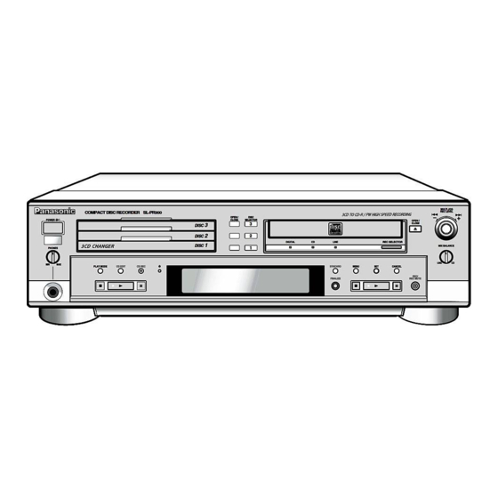
0V (3.5V) C292 R661 1/16 C291 R683 470p C661 R667 R670 QAX0599-001Z X651 D667 MA152WA-X C651 C652 R691 R695 OUTL OUT_L C691 C693 0.001 0.0027 C692 C694 0.001 0.0027 OUTR OUT_R R692 R696 SHEET SL-PR300(PP) CD SERVO, DETECTION SW SCHEMATIC DIAGRAM... - Page 83 Main Unit MULTI JOG REC LEVEL COMPACT DISC RECORDER SL-PR300 – OPEN / DISC POWER CLOSE SELECTOR OPEN / CLOSE DISC DISC DIGITAL LINE REC SELECTOR DISC MIX BALANCE PHONES LINE PLAY MODE CD EDIT CD REC SYNCHRO MENU CANCEL...
- Page 84 CD Control Operation Buttons PHONES LEVEL (Volume) Control PLAY MODE: Press repeatedly to select one of the play modes for Use this to adjust the volume being output to headphones con- the 3-CD changer. nected to the unit. CD EDIT: Press to select either Listening Edit or Program Note Edit recording mode.
- Page 85 Display Window PROGRAM RANDOM REPEAT ALL 1CD CD PLAYER CD RECORDER SYNCHRO SKIP ON ANALOG LISTENING EDIT HIGH SPEED AUTO TRACK DIGITAL 9 10 DAILY PROGRAM EDIT OVER 11 12 13 14 15 CD CD-R CD REC 1CD ONCE 44.1 CD–RW –...
- Page 86 Remote Control s (stop) Button Press to stop playback of the currently selected disc in the 3-CD changer or stop playback/recording of the disc in the CDR. DISC SELECTOR p (play) Button Press to play the currently selected CD. CD REC CD EDIT FINALIZE DISPLAY...
- Page 87 Digital IN J354 KEY3 S702~S708 CN841 IC331 COAXIAL selector Mix balance Operation IC311 MLOUT MROUT volume switch VR641 KEY4 OPTICAL S751~S756 IC722 DIGITAL IN J352 Operation P01~P35 switch 1G~16G S760~S762 FL Display Operation DI721 s witch SL-PR300(PP) S710, S721~S726 BLOCK DIAGRAM...
- Page 88 :These parts haven’t been used K358 D954 Q901 C201 D907 on the circuit. J871 C922 C353 D955 J351 B951 (These parts are not mentioned in J352 EP541 J354 J353 the “Schematic diagram” and the “Replacement parts list”.) SL-PR300(PP) MAIN P.C.B.
Need help?
Do you have a question about the SL-PR300 and is the answer not in the manual?
Questions and answers