Table of Contents
Advertisement
Wellmark Chemical Injection Solutions
11122 WEST LITTLE YORK RD
HOUSTON, TX 77041
Wellmark Website
Wellmark Mobile Support Site
(713) 466-3552
FEATURES
The DigiMax controller is designed to control chemical injection rates through
intermittent motor control. The 12VDC version is designed to be operated in off-
the-grid battery powered systems for upstream wellsite chemical injection. A
115VAC version is also available for applications where power is available.
Control Features Include
•
Auto Injection Mode - Enter injection rates directly using a
quarts/day input value.
characteristics of the pump and motor to determine cycle timing.
•
Manual Injection Mode - Directly enter ON and OFF timing to
manually controller injection rates and cycle timing.
•
Temperature Injection - Includes standard temperature sensor for
temperature-switched injection. Save chemical by disabling flow as
temperatures rise above a user defined setpoint.
•
Serial Communication - Modbus RTU communication via 2-wire
RS485 connection.
•
Onboard HMI - 8x2 LCD screen with 4 capacitive touch sense buttons
for local programming.
•
Voltage Monitoring (12VDC Versions) - Measures voltage
continuously, which may be used to help predict solar application
power failures when connected to a user's SCADA system.
•
Cycle Totalizer - Totalizes number of cycles ran to help analyze
injection rates. Can be manually reset.
•
Low Power - Screen backlight timeout conserves power when not in
use.
All programming selections made are retained upon power failure. Shutting the
main power switch off, or losing power will not affect controller settings upon
restart.
Contents
Specifications........................................................................................................ 1
Basic Operation..................................................................................................... 1
Viewing Current Settings............................................................................ 1
Setting Injection Mode and Rate............................................................... 2
Starting the Pump in Auto Mode...................................................... 2
Starting the Pump in Manual Mode................................................. 2
Pump Override.................................................................................... 2
Advanced Programming....................................................................................... 3
Adjusting Settings in the Programming Sub-Menu................................. 3
Resetting the Cycle Counter....................................................................... 3
Calibrating Temperature and Voltage....................................................... 3
Communication...................................................................................................... 4
Settings.......................................................................................................... 4
Modbus Map................................................................................................. 4
Troubleshooting..................................................................................................... 4
Replacement Parts....................................................................................... 4
Basic Troubleshooting.................................................................................. 4
Pump Displacement and Timer Settings............................................................. 5
General Pump Specifications...................................................................... 5
Manual Mode On / Off Times.................................................................... 5
12VDC, 30RPM Small Motor.............................................................. 5
12VDC, 64RPM Large Motor.......................................................... 6
115VAC, 60 RPM Motor (General Purpose)...................................... 7
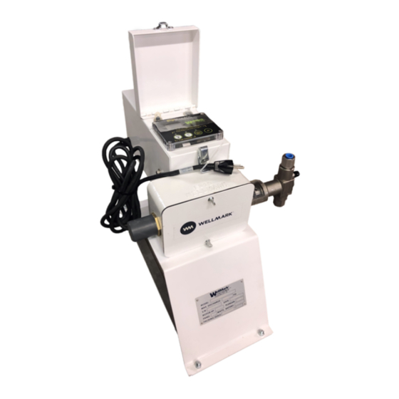
DigiMax Pump Controller
WELLMARK GENERAL PURPOSE DIGIMAX, 12VDC & 115VAC PUMPS
OPERATION/PROGRAMMING INSTRUCTIONS
The controller will use the physical
Specifications
Electrical Specifications
Specification
Input Voltage
Max Output Power
Max Current
Storage Temp Range
Operating
Temperature Range
Basic Operation
Viewing Current Settings
The DigiMax controller uses capacitive-sensing buttons. There is no general
contact with the buttons and only requires a light touch. When a button is
pressed the LED above it will illuminate, notifying the user that the input was
registered.
While in normal running mode, the DigiMax will cycle through a series of "Idle
Screens" to display current settings. Idle screens will vary based on the injection
mode setting-pressing any of the keys will cycle through the idle screens.
Manual Mode Screens
MOTOR
Current Cycle ON or OFF Time Remaining (Seconds)
CYCLES
Total Number of Cycles Recorded since Reset
TEMP MOD (Temperature Mode)
ON (Enabled) or OFF (Disabled)
TEMP SP (Temperature Setpoint)
Setpoint in °F (Current Temp also Displayed in °F)
VOLTAGE*
Current voltage in V
* Voltage output only displayed on 12VDC controllers
1
12VDC Control
115VAC Control
115VAC, 60Hz, Single
12VDC Nom +/- 3VDC
Phase
180W
345W
15A @ 12VDC
3A @ 115VAC
-30C to 70C
-20C to 70C
Auto Mode Screens
MTR SIZ (Motor Size)
Motor Output Speed (RPMS)
PLG SIZE (Plunger Size)
1/4", 3/8", or 1/2" Diameter
PIN POS (Pin Position)
1, 2, or 3
QTS/DAY (Quarts per Day)
Flow Rate Setpoint (Qts/Day)
REVISION 26-AUG-2021
Advertisement
Table of Contents

Summary of Contents for CHAMPIONX WELLMARK DigiMax
- Page 1 DigiMax Pump Controller WELLMARK GENERAL PURPOSE DIGIMAX, 12VDC & 115VAC PUMPS Wellmark Chemical Injection Solutions 11122 WEST LITTLE YORK RD HOUSTON, TX 77041 Wellmark Website OPERATION/PROGRAMMING INSTRUCTIONS Wellmark Mobile Support Site (713) 466-3552 FEATURES The DigiMax controller is designed to control chemical injection rates through intermittent motor control.
- Page 2 Setting Injection Mode and Rate Starting the Pump in Auto Mode the temperature sensor may be disconnected or malfunctioning if this does not match the current temperature. While on any idle screen, press (YES/+) and (EX) to enter program mode. Press (YES/+) and (EX) to save changes and exit the programming menu.
- Page 3 Advanced Programming Adjusting Settings in the Programming Sub-Menu Resetting the Cycle Counter To perform a cycle count reset: While on any idle screen, navigate to the standard programming menu by pressing (YES/+) and (EX) simultaneously. Press and hold ALL KEYS simultaneously while on any screen. Screen Ensure that OP MODE selection screen is shown, with the option set will remain blank while keys are held.
- Page 4 General Issues Communication Display Difficult to Read Settings • The DigiMax controller comes standard with an 8x2 LCD screen. In When serial communication is enabled in the programming sub-menu, this extremely cold temperatures (below ~-20°C), the DigiMax liquid device is capable of communicating to user’s SCADA systems for remote crystal display may become difficult to read or slow to respond.
- Page 5 Pump Displacement & Timer Settings General Pump Specifications 1/4” Plunger 3/8” Plunger 1/2” Plunger Plunger Area (in 0.0491 0.1104 0.1963 Pin Position Stroke Length (Inches) 0.624 0.874 1.124 0.624 0.874 1.124 0.624 0.874 1.124 Displacement per Stroke (Qts) 0.000531 0.000743 0.000956 0.001193 0.001671...
- Page 6 12VDC Motor, 64 RPM Large Motor (General Purpose) 1/4" Plunger 3/8" Plunger 1/2" Plunger Qts/Day Target Pin 1 Pin 2 Pin 3 Pin 1 Pin 2 Pin 3 Pin 1 Pin 2 Pin 3 1 / 119 1 / 119 1 / 119 1 / 119 2 / 118...
- Page 7 115VAC, 60 RPM Motor (General Purpose) 1/4" Plunger 3/8" Plunger 1/2" Plunger Qts/Day Target Pin 1 Pin 2 Pin 3 Pin 1 Pin 2 Pin 3 Pin 1 Pin 2 Pin 3 1 / 119 1 / 119 1 / 119 1 / 119 3 / 117 2 / 118...
Need help?
Do you have a question about the WELLMARK DigiMax and is the answer not in the manual?
Questions and answers