Advertisement
Quick Links
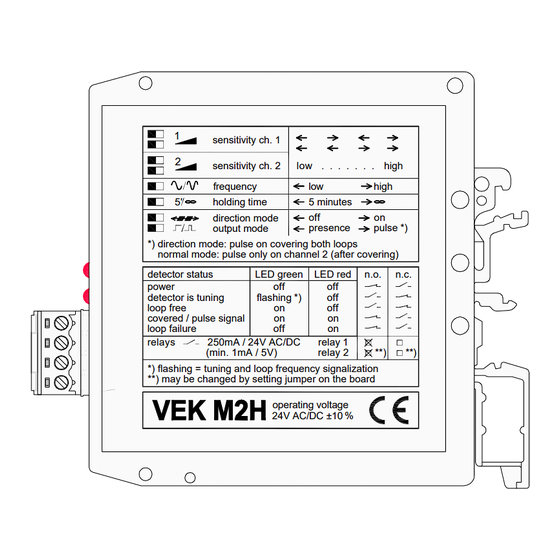
Loop Detector Layout
22.50
0V
24V
2b
1
sensitivity ch. 1
1
2
sensitivity ch. 2
2
frequency
5'
holding time
direction mode
5'
output mode
*) direction mode: pulse on covering both loops
normal mode: pulse only on channel 2 (after covering)
1
detector status
power
2
detector is tuning
loop free
covered / pulse signal
loop failure
1
relays
250mA / 24V AC/DC
(min. 1mA / 5V)
*) flashing = tuning and loop frequency signalization
2
**) may be changed by setting jumper on the board
1a
1b
2a
Connect Loops to
these terminals
Operating Instructions
1. Connect the power, ground, loop & output (See Terminal & Loop Connections).
2. Sensitivity of Loop 1 is set by switches `1` & `2` (See Function Settings).
3. Sensitivity of Loop 2 is set by switches `3` & `4` (See Function Settings).
Terminal Connections
Loop Connections
0V
24V
Loop 1
Loop 2
0V
24V 2b
L.E.D. Functions
Relay 2
1
Green Flashing, Red OFF:-
1a
1b 2a
Red OFF, Green OFF:-
Relay 1
Link Controls
Stuart Rd, Manor Park, Runcorn, Cheshire, WA7 1TS
T: +44 (0)1928 579050
F: +44 (0)1928 579259
www.linkcontrols.co.uk
sales@linkcontrols.co.uk
74.00
low . . . . . . . high
low
high
5 minutes
off
on
presence
pulse *)
LED green
LED red
n.o.
n.c.
off
off
flashing *)
off
on
off
on
on
off
on
relay 1
relay 2
**)
**)
operating voltage
24V AC/DC ±10 %
Detector is Tuning
Green ON, Red OFF:-
Loop Free
Red ON, Green ON:-
Loop is Covered
Green ON-OFF-ON:-
Pulse Output
Red ON, Green OFF:-
Loop Fail
Power OFF
Title:-
MFZ
Relay Function
As standard, both of the relays are Normally Open (N/O). To change Relay 2 to Normally Closed (N/C),
carefully open the detector housing and place the jumper (JP2) to the following position...
:Normally Open
Function
Loop Free
Loop Covered
Loop Fail
Detector is Tuning
Power Off
Note:- For additional information, please see side of loop detector
Function Settings
DIP Switches 1 & 2 :- Loop 1 sensitivity (4 steps)
MIN.
DIP Switches 3 & 4 :- Loop 2 sensitivity (4 steps)
MIN.
DIP Switch 5:- Frequency (High / Low)
:High
DIP Switch 6:- Holding time (5 mins - Infinity)
:5mins
Note:- Loop will recalibrate after 5 minutes constant detection
DIP Switch 7:- Direction detection
:Normal Operation
Note:- Directional operation is used for Traffic Management ONLY
DIP Switch 8:- Presence / Impulse selection
:Presence Operation
Note:- If Impulse operation is selected, the 1st loop to be activated will give a Presence signal when the
2nd loop is clear, a Pulse signal will then be given.
VEK M2H LOOP DETECTOR MODULE
(STOCK CODE: 37-4078)
:Normally Closed
MAX.
MAX.
:Low
:Infinite
:Directional Operation
:Impulse Operation
Drawing No:-
LC-1687
Revision No:-
B
Drawn By:-
S.B.P.
Checked By:-
R.A.H.
Page No:-
1 of 2
Rev Date:-
25/02/09
Date:-
26/11/99
Appr' By:-
S.L.
Advertisement

Summary of Contents for Link Controls VEK M2H
- Page 1 Drawing No:- LC-1687 Page No:- 1 of 2 Link Controls Revision No:- Rev Date:- 25/02/09 VEK M2H LOOP DETECTOR MODULE (STOCK CODE: 37-4078) Stuart Rd, Manor Park, Runcorn, Cheshire, WA7 1TS Drawn By:- S.B.P. Date:- 26/11/99 T: +44 (0)1928 579050...
- Page 2 Drawing No:- LC-1687 Page No:- 2 of 2 Link Controls Revision No:- Rev Date:- 25/02/09 VEK M2H LOOP DETECTOR MODULE (STOCK CODE: 37-4078) Stuart Rd, Manor Park, Runcorn, Cheshire, WA7 1TS Drawn By:- S.B.P. Date:- 26/11/99 T: +44 (0)1928 579050...
Need help?
Do you have a question about the VEK M2H and is the answer not in the manual?
Questions and answers