Table of Contents
Advertisement
Quick Links
EN
2
Manual No. SEP.SEPCOM_Vertical.--.M.A4.0722.EN
WAMGROUP S.p.A.
Via Cavour, 338
41030 Ponte Motta
Cavezzo (MO) - ITALY
SEPCOM
Vertical
SEPINDV, SEPPIGV - SOLID-LIQUID
SEPARATOR
ASSEMBLY AND
MAIN INSTRUCTIONS
FOR USE AND
MAINTENANCE
V2-200-3
Latest Update: July 2022
ORIGINAL INSTRUCTIONS IN ENGLISH
V2-150-3
Issue: A4
+ 39 / 0535 / 618111
fax
+ 39 / 0535 / 618226
e-mail
info@wamgroup.com
internet
www.wamgroup.com
®
Advertisement
Table of Contents

Related Manuals for WAMGROUP SEPCOM Vertical

Summary of Contents for WAMGROUP SEPCOM Vertical
- Page 1 MAINTENANCE V2-200-3 V2-150-3 Manual No. SEP.SEPCOM_Vertical.--.M.A4.0722.EN Issue: A4 Latest Update: July 2022 ORIGINAL INSTRUCTIONS IN ENGLISH WAMGROUP S.p.A. + 39 / 0535 / 618111 Via Cavour, 338 + 39 / 0535 / 618226 41030 Ponte Motta e-mail info@wamgroup.com Cavezzo (MO) - ITALY internet www.wamgroup.com...
- Page 2 All the products described in this catalogue are manufactured according to WAMGROUP S.p.A. Quality System procedures. The Company’s Quality System, certified in July 1994 according to International Standards UNI EN ISO 9002 and extended to the latest release of UNI EN ISO 9001, ensures that the entire production process, starting from the processing of the order to the technical service after delivery, is carried out in a controlled manner that guarantees the quality standard of the product.
-
Page 3: Table Of Contents
SEPCOM Vertical 07.22 ® INDEX SEP.SEPCOM_Vertical.--.M.A4.0722.EN Issue: A4 TABLE OF CONTENTS 1.0 GENERAL INFORMATION ........................1 1.1 Scope of the Manual ......................... 1 1.2 Symbols ............................2 1.3 Glossary and terminology ......................... 4 1.4 Manufacturer’s data and identification of equipment ................. 5 1.5 Request for assistance ........................ - Page 4 SEPCOM Vertical 07.22 ® INDEX SEP.SEPCOM_Vertical.--.M.A4.0722.EN Issue: A4 7.0 INFORMATION REGARDING MAINTENANCE ..................35 7.1 Scheduled maintenance table ......................35 7.2 Cleaning the equipment (the machine) ...................35 7.3 Cleaning the screen ........................36 7.4 Gear reducer lubrication ........................36 7.5 Changing the oil ..........................37 8.0 REPLACEMENT OF PARTS ........................38 8.1 Safety recommendations for replacement ..................38 8.2 Replacing the electric motor ......................38...
-
Page 5: General Information
SEPCOM Vertical 07.22 ® 1.0 GENERAL INFORMATION SEP.SEPCOM_Vertical.--.M.A4.0722.EN Issue: A4 1.1 Scope of the Manual This Manual has been prepared by the Manufacturer to provide the operating technical information for instal- lation, operation and maintenance of the equipment concerned. The Manual, which is an integral part of the equipment concerned, must be preserved throughout the life of the equipment in a known easily accessible place, available for consultation whenever required. -
Page 6: Symbols
SEPCOM Vertical 07.22 ® 1.0 GENERAL INFORMATION SEP.SEPCOM_Vertical.--.M.A4.0722.EN Issue: A4 1.2 Symbols To highlight certain parts of the text, for purposes of safety, or to indicate important information, certain symbols are used, the meaning of which is described below. It is important to comply with and scrupulously follow the information highlighted by the symbols. Danger - Warning Indicates situations of serious danger which, if ignored, can be risky for the health and safety of per- sons. - Page 7 SEPCOM Vertical 07.22 ® 1.0 GENERAL INFORMATION SEP.SEPCOM_Vertical.--.M.A4.0722.EN Issue: A4 List of safety and information symbols Symbol Symbol description representation Danger sign: indicates danger of electric shock caused by the presence of powered components inside the junction box or control panel. Obligation: read this Manual before carrying out any action on the equipment con- cerned.
-
Page 8: Glossary And Terminology
SEPCOM Vertical 07.22 ® 1.0 GENERAL INFORMATION SEP.SEPCOM_Vertical.--.M.A4.0722.EN Issue: A4 1.3 Glossary and terminology Operator: person appropriately trained and authorized by the Production Manager for setting up the equip- ment concerned and carrying out routine maintenance. Installer: organization with specialized technicians and appropriate equipment for carrying out risk-free instal- lation and extraordinary maintenance. -
Page 9: Manufacturer's Data And Identification Of Equipment
The plates show the reference necessary for operating safety. SEPCOM Vertical ® 1 - Gear reducer identification plate Year WAMGROUP A) Year of manufacture WAM S.p.A. v. Cavour 338 Ponte Motta/Cavezzo (MO)-ITALY B) Manufacturer’s name and address C) Identification of gear reducer... -
Page 10: Request For Assistance
SEPCOM Vertical 07.22 ® 1.0 GENERAL INFORMATION SEP.SEPCOM_Vertical.--.M.A4.0722.EN Issue: A4 2 - Identification of the separator Year The plate is fixed to the lower side of the feeding hop- per. Strada degli Schiocchi, 12 MODENA (MO) - ITALY TYPE: A) Year of manufacture Serial N0.: B) Manufacturer’s name and address C) Separator type... -
Page 11: Exclusion Of Responsibility
SEPCOM Vertical 07.22 ® 1.0 GENERAL INFORMATION SEP.SEPCOM_Vertical.--.M.A4.0722.EN Issue: A4 1.7 Exclusion of responsibility The equipment is delivered according to the specifications indicated by the Buyer in the order and the condi- tions valid at the time of purchase. The Manufacturer shall not accept responsibility for safety of persons or objects and operation failure of the equipment if the loading/unloading operations from trucks, transport, positioning at the site, use, repairs, main- tenance etc. -
Page 12: Information Regarding Safety
SEPCOM Vertical 07.22 ® 2.0 INFORMATION REGARDING SAFETY SEP.SEPCOM_Vertical.--.M.A4.0722.EN Issue: A4 2.1 General safety prescriptions Read the Instruction Manual carefully and strictly follow the instructions it includes, especially those regarding safety. Most accidents at the workplace are caused by negligence, failure to follow the most elementary safety regulations and incorrect or improper use of tools and equipment. -
Page 13: Safety Prescriptions For Installation
SEPCOM Vertical 07.22 ® 2.0 INFORMATION REGARDING SAFETY SEP.SEPCOM_Vertical.--.M.A4.0722.EN Issue: A4 2.3 Safety prescriptions for installation Before starting with installation, a “Safety Plan” must be implemented to safeguard the personnel di- rectly involved and those who carry out operations in the surrounding area. All the laws must be strictly applied, especially those concerning workplace safety. -
Page 14: Safety Recommendations On Biological Risks
SEPCOM Vertical 07.22 ® 2.0 INFORMATION REGARDING SAFETY SEP.SEPCOM_Vertical.--.M.A4.0722.EN Issue: A4 Apart from invalidation of the warranty, the Manufacturer declines all responsibility for damage to objects and harm to persons deriving from the use of non-original spare parts or due to modifications made during repairs without express written authorization. -
Page 15: Technical Information
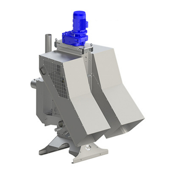
SEPCOM Vertical 07.22 ® 3.0 TECHNICAL INFORMATION SEP.SEPCOM_Vertical.--.M.A4.0722.EN Issue: A4 3.1 General description of equipment SEPCOM Vertical is a solid-liquid screw press type separators. ® For the proper operation of the equipment it is important for the fluid to be processed to be pumpable. The separator consists of: - inlet module - separation and conveying module... -
Page 16: Main Components
SEPCOM Vertical 07.22 ® 3.0 TECHNICAL INFORMATION SEP.SEPCOM_Vertical.--.M.A4.0722.EN Issue: A4 3.2 Main components SEPCOM Vertical ® Item Description Diaphragm pressor Load-bearing structure Screen basket Screws Liquid phase discharging hopper Compensator tank Material inlet pipe Overflow Venting air pipe Support feet Motor and gear reducer. -
Page 17: Operating Principle
SEPCOM Vertical 07.22 ® 3.0 TECHNICAL INFORMATION SEP.SEPCOM_Vertical.--.M.A4.0722.EN Issue: A4 3.3 Operating principle The material to be separated is fed by means of a pump into the separator and then inside the separator where it gets conveyed by the two screw into the screen. The diaphragm applies a counterpressure that squeezes the material and pushes the liquid fraction through the screen basket. -
Page 18: Noise Level
SEPCOM Vertical 07.22 ® 3.0 TECHNICAL INFORMATION SEP.SEPCOM_Vertical.--.M.A4.0722.EN Issue: A4 Important It is forbidden to use the equipment for materials reaching a temperatures value higher than 60°C; in case of outdoor temperatures below 0°C, the equipment has to be provided with the necessary protec- tions. -
Page 19: Safety And Information Signs
Follow the signs on the plates. Ensure the plates are legible; otherwise clean them and replace the damaged ones, applying them in their original position. SEPCOM Vertical N.B.: See the page 2, 1.2 Symbols Danger - Warning Danger of shearing and dragging: do not insert the limbs inside the separator. -
Page 20: Safety Devices
SEPCOM Vertical 07.22 ® 3.0 TECHNICAL INFORMATION SEP.SEPCOM_Vertical.--.M.A4.0722.EN Issue: A4 3.10 Safety devices Inspection hatches: The access to inspections hatches is not necessary during operation of the equipment; their use is meant for routine or extraordinary maintenance operations. Danger - Warning Before starting up the machine, it is compulsory closing the inspection hatches by fitting the screws provided in their original position to avoid they accidentally open. - Page 21 SEPCOM Vertical 07.22 ® 3.0 TECHNICAL INFORMATION SEP.SEPCOM_Vertical.--.M.A4.0722.EN Issue: A4 Safety switches: The SEPCOM Vertical separator is equipped with two safety devices which allow the shut-down of the sepa- ® rator after the opening of the chutes for the separated solids to perform maintenance operations in complete safety.
- Page 22 SEPCOM Vertical 07.22 ® 3.0 TECHNICAL INFORMATION SEP.SEPCOM_Vertical.--.M.A4.0722.EN Issue: A4 Safety systems: The safety pin shown in the image below is supplied with the separator SEPCOM Vertical. ® The safety pin block the chutes opened to prevent them from accidentally get closed which would cause the euipment tostart up.
-
Page 23: Information Regarding Handling And Transport
SEPCOM Vertical 07.22 ® 4.0 INFORMATION REGARDING HANDLING AND TRANSPORT SEP.SEPCOM_Vertical.--.M.A4.0722.EN Issue: A4 4.1 Type of packaging The list shows the description and symbols envisaged on the packing. A) Fragile: indicates that the package has to be handled and lifted carefully to avoid damage. - Page 24 SEPCOM Vertical 07.22 ® 4.0 INFORMATION REGARDING HANDLING AND TRANSPORT SEP.SEPCOM_Vertical.--.M.A4.0722.EN Issue: A4 Type of packaging available STD. PACKAGING WITH PALLET + NYLON SHRINK-WRAP Important The centre of gravity in the picture above is only an indicative in relation to the packed equipment. However, all necessary precautions must always be taken to handle the material correctly.
-
Page 25: Reception Of Goods
SEPCOM Vertical 07.22 ® 4.0 INFORMATION REGARDING HANDLING AND TRANSPORT SEP.SEPCOM_Vertical.--.M.A4.0722.EN Issue: A4 4.2 Reception of goods On receiving the goods, ensure that the type and quantity correspond to the data present on the acknowledge- ment of order. Possible damage has to be immediately communicated in writing in the space provided to this purpose in the waybill. - Page 26 SEPCOM Vertical 07.22 ® 4.0 INFORMATION REGARDING HANDLING AND TRANSPORT SEP.SEPCOM_Vertical.--.M.A4.0722.EN Issue: A4 Lift the separator and handle it by means of the belts according to the picture. Danger - Warning Harness the microfilter by means of the safety hooks. DO NOT use clamps, rings, open hooks or sys- tems that do not ensure the necessary safety level.
-
Page 27: Installation And Fixing
SEPCOM Vertical 07.22 ® 5.0 INSTALLATION AND FIXING SEP.SEPCOM_Vertical.--.M.A4.0722.EN Issue: A4 5.1 Safety prescriptions for installation Danger - Warning The replacement operations must be carried out by a specialist authorized technician with specific skills. Provide appropriate safety measures and use suitable equipment to prevent risk of work accident to persons involved in the operations and to those nearby. - Page 28 SEPCOM Vertical 07.22 ® 5.0 INSTALLATION AND FIXING SEP.SEPCOM_Vertical.--.M.A4.0722.EN Issue: A4 3) Fix sturdily the compensator tank by means of the special brajet to the struc- ture of the separator by means of bolts. 4) Fix sturdily the compensator tank to the inlet of the separator by means of bolts.
-
Page 29: Fixing Of The Support Frame
SEPCOM Vertical 07.22 ® 5.0 INSTALLATION AND FIXING SEP.SEPCOM_Vertical.--.M.A4.0722.EN Issue: A4 5.3 Fixing of the support frame Separator V2-200-3 Separator V2-150-3 seen from the bottom seen from the bottom Weight of the separator (kg) Model (empty) (while running on empty) V2-150-3 V2-200-3 1161... -
Page 30: Assembly
SEPCOM Vertical 07.22 ® 5.0 INSTALLATION AND FIXING SEP.SEPCOM_Vertical.--.M.A4.0722.EN Issue: A4 5.4 Assembly As previously highlighted, it is important a correct installation of the system as well as the operation according to the permitted use indications in order to ensure the proper functioning of the separator. The drawing below represents the plant layout to be followed for the installation of the separator SEPCOM Vertical. - Page 31 SEPCOM Vertical 07.22 ® 5.0 INSTALLATION AND FIXING SEP.SEPCOM_Vertical.--.M.A4.0722.EN Issue: A4 FEEDING PUMP The feeding pump (B) is positioned 400 / 500 mm (H1) from the bottom of the tank (A) for the product to be treated to prevent foreign solid bodies from entering. Consider in a rated cross-section (Q) ø...
-
Page 32: Electrical Connections And Motor Wiring Diagram
SEPCOM Vertical 07.22 ® 5.0 INSTALLATION AND FIXING SEP.SEPCOM_Vertical.--.M.A4.0722.EN Issue: A4 5.5 Electrical connections and motor wiring diagram The access to the junction box has to be permitted to specialized personnel only. Before carrying out the connections make sure the voltage matches the values given on the rating plate. Make sure the safety standards are followed. - Page 33 SEPCOM Vertical 07.22 ® 5.0 INSTALLATION AND FIXING SEP.SEPCOM_Vertical.--.M.A4.0722.EN Issue: A4 In case of reverse rotation, after having disconnected from the mains, reverse the position of the power cables inside the terminal box. (see image below)
-
Page 34: Electrical Connection
SEPCOM Vertical 07.22 ® 5.0 INSTALLATION AND FIXING SEP.SEPCOM_Vertical.--.M.A4.0722.EN Issue: A4 5.6 Electrical connection Danger - Warning The equipment is not provided with an electrical system. Connection to the mains has to be carried out by an electrician. Provide mains supply to the equipment concerned according to the compliant current legislation and take into consideration the safety measures required by the installation environment and the envis- aged operating conditions. -
Page 35: Inspection
SEPCOM Vertical 07.22 ® 5.0 INSTALLATION AND FIXING SEP.SEPCOM_Vertical.--.M.A4.0722.EN Issue: A4 5.7 Inspection Important When installation is complete, authorized personnel must carry out a general test to ensure that the safety conditions have been completely satisfied. The authorized personnel must also check: - that no tools or other material have been forgotten inside the equipment. -
Page 36: Information Regarding Use
SEPCOM Vertical 07.22 ® 6.0 INFORMATION REGARDING USE SEP.SEPCOM_Vertical.--.M.A4.0722.EN Issue: A4 6.1 Gear reducer Important In case of excessive noise, strong vibrations, etc. stop the separator and report the problem to the person in charge authorized to restore the correct working. Do not use the separator if faulty. -
Page 37: Start Up And Normal Operation
SEPCOM Vertical 07.22 ® 6.0 INFORMATION REGARDING USE SEP.SEPCOM_Vertical.--.M.A4.0722.EN Issue: A4 6.2 Start up and normal operation When starting up the separator for the first time, and generally for operating the equipment after prolonged shut-downs, follow the procedure described below, after having checked the electric and hydraulic connections to the equipment: 1) Start the separator (fixed speed). -
Page 38: Reuse After Long Shut-Down
SEPCOM Vertical 07.22 ® 6.0 INFORMATION REGARDING USE SEP.SEPCOM_Vertical.--.M.A4.0722.EN Issue: A4 Section view of the overflow To run your machine at its best, the filling level of the overflow section must range between 1/2 and 2/3 of the full section. 6.3 Reuse after long shut-down Important If the equipment is to be used in different conditions and with materials other than the previous applica-... -
Page 39: Sep.sepcom_Vertical.--.M.a4.0722.En Issue: A4
SEPCOM Vertical 07.22 ® 7.0 INFORMATION REGARDING MAINTENANCE SEP.SEPCOM_Vertical.--.M.A4.0722.EN Issue: A4 Danger - Warning Before carrying out any maintenance operation, enable all safety devices to ensure the safety of the persons involved in the operations and those nearby. Set the equipment concerned in safety condition. Wear suitable personal protection equipment;... -
Page 40: Cleaning The Screen
SEPCOM Vertical 07.22 ® 7.0 INFORMATION REGARDING MAINTENANCE SEP.SEPCOM_Vertical.--.M.A4.0722.EN Issue: A4 7.3 Cleaning the screen Remove the screen basket as indicated at page 50 (Replacing the screen). Wash the screen basket with a hot water jet to remove all solid particles and crusts on the mesh. Then reposition the screen inside the separator by paying attention to insert it in the right direction. -
Page 41: Changing The Oil
SEPCOM Vertical 07.22 ® 7.0 INFORMATION REGARDING MAINTENANCE SEP.SEPCOM_Vertical.--.M.A4.0722.EN Issue: A4 7.5 Changing the oil Important Do not dump used oil in the environment but dispose it off in accordance with the laws in force regard- ing the matter. Follow the indications bellow: 1) Place a container of adequate capacity under the drainage plug (C). -
Page 42: Replacement Of Parts
SEPCOM Vertical 07.22 ® 8.0 REPLACEMENT OF PARTS SEP.SEPCOM_Vertical.--.M.A4.0722.EN Issue: A4 8.1 Safety recommendations for replacement Danger - Warning The replacement operations must be carried out by a specialist authorized technician with specific skills in the sector concerned (mechanical, electrical etc.). Prior to performing any operation: 1) Provide appropriate safety measures and use suitable equipment to prevent risk of work accident to persons involved in the operations and to those nearby. - Page 43 SEPCOM Vertical 07.22 ® 8.0 REPLACEMENT OF PARTS SEP.SEPCOM_Vertical.--.M.A4.0722.EN Issue: A4 Assembly Follow the indications bellow: 1) Wipe the coupling surfaces of the new motor and gear reducer thoroughly. 2) Lubricate the shaft (E) of the electric motor and the corresponding seat (F) of the gear reducer with the prescribed lubricant (see “Table of lubricants and sealants”).
-
Page 44: Replacing The Screw
SEPCOM Vertical 07.22 ® 8.0 REPLACEMENT OF PARTS SEP.SEPCOM_Vertical.--.M.A4.0722.EN Issue: A4 8.3 Replacing the screws 1) Open the chute from the outlet side, according to the picture. 2) Unhook the quick-release coupling of the guard. 3) Remove the guard by grasping the handle. - Page 45 SEPCOM Vertical 07.22 ® 8.0 REPLACEMENT OF PARTS SEP.SEPCOM_Vertical.--.M.A4.0722.EN Issue: A4 4) Unscrew the fixing bolts of the screen basket fixing bars and of the compaction module. 5) Remove the fixing bars, the screen and the compaction module. 6) Unscrew the grub screws indicated by the red arrow to unlock the to unlock the rings which hold the sections of the two augers.
- Page 46 SEPCOM Vertical 07.22 ® 8.0 REPLACEMENT OF PARTS SEP.SEPCOM_Vertical.--.M.A4.0722.EN Issue: A4 8) Lift up the augers from their seat and re- move them out of the separator. Check or replace the auger and follow the indications above in reversed order to fit back the augers. Important For a correct repositioning of the two augers keep the alignment of the two notches according to the figure.
- Page 47 SEPCOM Vertical 07.22 ® 8.0 REPLACEMENT OF PARTS SEP.SEPCOM_Vertical.--.M.A4.0722.EN Issue: A4 Important Before closing back the chutes to release first the safety pin (see image below).
-
Page 48: Replacing The Screw Sections
SEPCOM Vertical 07.22 ® 8.0 REPLACEMENT OF PARTS SEP.SEPCOM_Vertical.--.M.A4.0722.EN Issue: A4 8.4 Replacing the screw sections To replace the sections, remove first the auger by following the instructions provided at Chapter 8.3 "Replacing the screw." Once the auger has been removed, proceed with the replacement of the sections as follows: 1) Remove the fixing screw of the upper hub. - Page 49 SEPCOM Vertical 07.22 ® 8.0 REPLACEMENT OF PARTS SEP.SEPCOM_Vertical.--.M.A4.0722.EN Issue: A4 5) Remove the engineering polymer section. Remove the worn or damaged sections and repeat the steps priorly mentioned in reversed order. Prior to replacing the sections, clean them as well as the inside of the microfilter. Prior to inserting the sections, lubricate the shaft.
- Page 50 SEPCOM Vertical 07.22 ® 8.0 REPLACEMENT OF PARTS SEP.SEPCOM_Vertical.--.M.A4.0722.EN Issue: A4 Important See the Technical Catalogue for the proper sequence. LEFT SIDE (SX) RIGHT SIDE (DX) Important Pay attention to the side (left or right) on which the modules of the screw have has to be installed. The correct installation side is shown on each module with the abbreviation SX (LH) for left side and DX (RH) for the right side.
-
Page 51: Inspecting The Screen
SEPCOM Vertical 07.22 ® 8.0 REPLACEMENT OF PARTS SEP.SEPCOM_Vertical.--.M.A4.0722.EN Issue: A4 8.5 Inspecting the screen 1) Open the chute according to the picture. 2) Unhook the quick-release coupling of the guard. 3) Remove the guard by grasping the handle. - Page 52 SEPCOM Vertical 07.22 ® 8.0 REPLACEMENT OF PARTS SEP.SEPCOM_Vertical.--.M.A4.0722.EN Issue: A4 4) The screen can now be dismantled. Important Before closing back the chutes to release first the safety pin (see image below).
- Page 53 SEPCOM Vertical 07.22 ® 8.0 REPLACEMENT OF PARTS SEP.SEPCOM_Vertical.--.M.A4.0722.EN Issue: A4 8.5.1 Cleaning or replacing the screen 1) Open the chute according to the picture. 2) Unhook the quick-release coupling of the guard. 3) Remove the guard by grasping the handle.
- Page 54 SEPCOM Vertical 07.22 ® 8.0 REPLACEMENT OF PARTS SEP.SEPCOM_Vertical.--.M.A4.0722.EN Issue: A4 4) Unscrew the fixing bolts of the screen basket fixing bars and of the compaction module. 5) Remove the fixing bars, the screen and the compaction module. Wash the screen with pressurized hot water. Important Repeat the same operations for the screen installed on the other side of the separator.
-
Page 55: Replacing The Mechanical Seal Of The Lower Bearings
SEPCOM Vertical 07.22 ® 8.0 REPLACEMENT OF PARTS SEP.SEPCOM_Vertical.--.M.A4.0722.EN Issue: A4 8.6 Replacing the mechanical seal of the lower bearings 1) Open the chute according to the picture. 2) Unhook the quick-release coupling of the guard. 3) Remove the guard by grasping the handle. - Page 56 SEPCOM Vertical 07.22 ® 8.0 REPLACEMENT OF PARTS SEP.SEPCOM_Vertical.--.M.A4.0722.EN Issue: A4 4) Unscrew the fixing bolts of the screen basket fixing bars and of the compaction module. 5) Remove the fixing bars, the screen and the compaction module. 6) Unscrew the grub screws indicated by the red arrow to unlock the to unlock the rings which hold the sections of the two augers.
- Page 57 SEPCOM Vertical 07.22 ® 8.0 REPLACEMENT OF PARTS SEP.SEPCOM_Vertical.--.M.A4.0722.EN Issue: A4 8) Lift up the augers from their seat and re- move them out of the separator. 9) Untighten the fixing screws of the inspec- tion hatch and remove it. 10) Disconnect greasing pipe from the quick- release coupling.
- Page 58 SEPCOM Vertical 07.22 ® 8.0 REPLACEMENT OF PARTS SEP.SEPCOM_Vertical.--.M.A4.0722.EN Issue: A4 12) Slip out the supports unit from the ma- chine body. 13) Unscrew the screws that secure the cover to the bearings and seals support. 14) Remove the cover from the bearings and seals support.
- Page 59 SEPCOM Vertical 07.22 ® 8.0 REPLACEMENT OF PARTS SEP.SEPCOM_Vertical.--.M.A4.0722.EN Issue: A4 16) Remove the locking washer from the bearings and seals support. 17) Pull the seals and bearings unit from the seals support by pushing the seals and bearings unit upwards. 18) Remove the first bushing.
- Page 60 SEPCOM Vertical 07.22 ® 8.0 REPLACEMENT OF PARTS SEP.SEPCOM_Vertical.--.M.A4.0722.EN Issue: A4 19) Remove the first inner and outer spacer. 20) Remove the second bearing. Important Replace the faulty bearing.
- Page 61 SEPCOM Vertical 07.22 ® 8.0 REPLACEMENT OF PARTS SEP.SEPCOM_Vertical.--.M.A4.0722.EN Issue: A4 21) Remove the second spacer. 22) Slip out the mechanical seals one by one. Important Replace the damaged seals.
- Page 62 SEPCOM Vertical 07.22 ® 8.0 REPLACEMENT OF PARTS SEP.SEPCOM_Vertical.--.M.A4.0722.EN Issue: A4 23) Remove the grains that secure the protec- tive bushing to the shaft. 24) Remove the protective bushing.
- Page 63 SEPCOM Vertical 07.22 ® 8.0 REPLACEMENT OF PARTS SEP.SEPCOM_Vertical.--.M.A4.0722.EN Issue: A4 25) Remove the sealing ring. Important Replace the worn ring with the spare one. 26) Fit the new sealing ring. 27) Insert the protective bushing on the shaft and secure it with the dowels provided.
- Page 64 SEPCOM Vertical 07.22 ® 8.0 REPLACEMENT OF PARTS SEP.SEPCOM_Vertical.--.M.A4.0722.EN Issue: A4 Important Fit a new protective bushing with new nuts; make sure the nuts do not protrude out of the bushing. 28) Fit the mechanical seals one by one. 29) Fit the second spacer.
- Page 65 SEPCOM Vertical 07.22 ® 8.0 REPLACEMENT OF PARTS SEP.SEPCOM_Vertical.--.M.A4.0722.EN Issue: A4 30) Fit the second bearing. 31) Fit the first inner and outer spacer.
- Page 66 SEPCOM Vertical 07.22 ® 8.0 REPLACEMENT OF PARTS SEP.SEPCOM_Vertical.--.M.A4.0722.EN Issue: A4 32) Fit the first bearing. 33) Fit the seals and bearings unit on the seals support by pushing the seals and bearings unit upwards. 34) Fit the locking washer on the bearings and seals support.
- Page 67 SEPCOM Vertical 07.22 ® 8.0 REPLACEMENT OF PARTS SEP.SEPCOM_Vertical.--.M.A4.0722.EN Issue: A4 35) Tighten the locking screw. 36) Fit the cover on the bearings and seals support. 37) Tighten the screws that secure the cover to the bearings and seals support.
- Page 68 SEPCOM Vertical 07.22 ® 8.0 REPLACEMENT OF PARTS SEP.SEPCOM_Vertical.--.M.A4.0722.EN Issue: A4 38) Fit the supports unit on the machine body. 39) Tighten the fixing screws on the support units of the machine body. 40) Connect the greasing pipe to the quick- release coupling.
- Page 69 SEPCOM Vertical 07.22 ® 8.0 REPLACEMENT OF PARTS SEP.SEPCOM_Vertical.--.M.A4.0722.EN Issue: A4 Important Before closing back the chutes to release first the safety pin (see image below).
-
Page 70: Disassembling The Gear Reducer
SEPCOM Vertical 07.22 ® 8.0 REPLACEMENT OF PARTS SEP.SEPCOM_Vertical.--.M.A4.0722.EN Issue: A4 8.7 Disassembling the gear reducer 1) Open the chute from the outlet side, according to the picture. 2) Unhook the quick-release coupling of the guard. 3) Remove the guard by grasping the handle. - Page 71 SEPCOM Vertical 07.22 ® 8.0 REPLACEMENT OF PARTS SEP.SEPCOM_Vertical.--.M.A4.0722.EN Issue: A4 4) Unscrew the fixing bolts of the screen basket fixing bars and of the compaction module. 5) Remove the fixing bars, the screen and the compaction module. 6) Unscrew the grub screws indicated by the red arrow to unlock the to unlock the rings which hold the sections of the two augers.
- Page 72 SEPCOM Vertical 07.22 ® 8.0 REPLACEMENT OF PARTS SEP.SEPCOM_Vertical.--.M.A4.0722.EN Issue: A4 8) Lift up the augers from their seat and re- move them out of the separator. 9) Open the chute at the outlet side. 10) Remove the front guards on both sides by unscrewing the indicated screws.
- Page 73 SEPCOM Vertical 07.22 ® 8.0 REPLACEMENT OF PARTS SEP.SEPCOM_Vertical.--.M.A4.0722.EN Issue: A4 11) Remove the front guards on both sides by unscrewing the indicated screws. 12) Untighten and remove completely the screw no. 1. Slacken the screw no. 2. Carry out the same steps for the guard on the opposite side.
- Page 74 SEPCOM Vertical 07.22 ® 8.0 REPLACEMENT OF PARTS SEP.SEPCOM_Vertical.--.M.A4.0722.EN Issue: A4 14) Lift the guard up according to the picture. Carry out the same steps for the guard on the opposite side. 15) Remove the side guards. 16) Disconnect greasing pipe. 17) Remove the fixing screws of the drive unit.
- Page 75 SEPCOM Vertical 07.22 ® 8.0 REPLACEMENT OF PARTS SEP.SEPCOM_Vertical.--.M.A4.0722.EN Issue: A4 18) Hook the 4 eyebolts through a chain with lifting hook having the proper size (capacity 180 kg). 19) Lift the drive unit. 20) Place the drive unit on a working bench and disassemble the motor.
- Page 76 SEPCOM Vertical 07.22 ® 8.0 REPLACEMENT OF PARTS SEP.SEPCOM_Vertical.--.M.A4.0722.EN Issue: A4 21) Remove the fixing screws of the gear reducer. 22) Remove the gear reducer. Install back the screen by following the steps previously indicate and restore the operation of the equipment. Important Before closing back the chutes to release first the safety pin (see image below).
-
Page 77: Returning The Equipment (The Machine)
SEPCOM Vertical 07.22 ® 8.0 REPLACEMENT OF PARTS SEP.SEPCOM_Vertical.--.M.A4.0722.EN Issue: A4 8.8 Returning the equipment (the machine) When returning the equipment (machine) use the original packaging if it has been preserved, otherwise fix the it on a pallet and cover it with nylon shrink-wrap, to protect it as best as possible from impact during transport. In any event, make sure there is no residue material inside the equipment (machine). -
Page 78: Information Regarding Faults
SEPCOM Vertical 07.22 ® 9.0 INFORMATION REGARDING FAULTS SEP.SEPCOM_Vertical.--.M.A4.0722.EN Issue: A4 9.1 Trouble-shooting Minor problems can be solved without consulting a specialist. The following Table contains a list of the most common problems, the possible causes and possible remedies. For particularly difficult actions which are not mentioned in the Table, contact the Manufacturer’s Customer Service Department. -
Page 79: Check-List In Case Of Fault
SEPCOM Vertical 07.22 ® 9.0 INFORMATION REGARDING FAULTS SEP.SEPCOM_Vertical.--.M.A4.0722.EN Issue: A4 9.2 Check-list in case of fault If you have been unable to solve the problem on the equipment (machine) even after having carried out the operations suggested in paragraph “Trouble-shooting” please contact the plant technician/installer/or the Manufacturer. -
Page 80: Aattachments
SEPCOM Vertical 07.22 ® A ATTACHMENTS SEP.SEPCOM_Vertical.--.M.A4.0722.EN Issue: A4 A3 Drive unit lubricants Table The Manufacturer mineral synthetic oil (LUKOIL STEELO HST 220) having a viscosity grade compliant with ISO VG. Mineral oil Brand BLASIA 220 (*) AGIP DEGOL BG220 ARAL ENERGOL GR - XP220 NL GEAR COMPOUND 220... -
Page 81: A2 Lubricants Table For Mechanical Parts
SEPCOM Vertical 07.22 ® A ATTACHMENTS SEP.SEPCOM_Vertical.--.M.A4.0722.EN Issue: A4 A2 Lubricants table for mechanical parts The lubricants brands are in alphabetic order without any reference to the product quality. The list does not cover the entire range of lubricants. It is therefore possible to use other lubricants as long as they have the same characteristics.
Need help?
Do you have a question about the SEPCOM Vertical and is the answer not in the manual?
Questions and answers