
Summary of Contents for Hamamatsu Energetiq LDTLS TLS-EQ-9
- Page 1 Model TLS-EQ-9 Laser-Driven Tunable Light Source LDTLS ® Operation Manual Revision 3, June 2022 Part Number DOC-9220...
- Page 2 ©2022 Energetiq Technology, Inc. All rights reserved. Energetiq products are covered by the following patents: US 7435982, 7786455, 8525138, 8969841, 9048000, 9185786; Japan 5410958, 5628253; Korea 10-1507617; UK GB2450045. All technical information, including drawings, schematics and specifications contained in this document are the property of Energetiq and shall not be reproduced in whole or in part without the written consent of Energetiq.
-
Page 4: Table Of Contents
Table of Contents Introduction ............................1 Safety instructions ..........................1 2.1. General Precautions ........................1 2.2. Definition of equipment and document symbols and designations ..........2 2.3. Laser Information .......................... 3 2.4. Labels and Safety Notification....................... 4 2.5. Safety Interlocks ..........................5 2.6. - Page 5 7.1.2 Procedure ..........................15 7.2. Fault Indicator Block Diagram ..................... 20 Warranty .............................. 21 Appendix .............................. 21 9.1. Dimensional Drawings ........................ 21 9.2. Environmental Requirements ...................... 22 9.3. I/O Connector Pin Assignment ....................22 9.4. RS-485 Interface Pin Assignment ....................22 9.5.
-
Page 6: Introduction
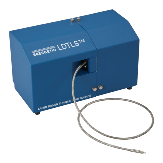
1. Introduction The TLS-EQ-9 Laser Driven Tunable Light Source is a compact, highly stable tunable light source. It utilizes the Energetiq EQ-9 Laser Driven Light Source® as a broadband light source. A monochromator is used to select the desired output wavelength. The monochromator output is fiber coupled to the TLS-EQ-9 output. -
Page 7: Definition Of Equipment And Document Symbols And Designations
WARNING: This unit emits ultraviolet (UV) radiation that is harmful to humans. Avoid exposure to the direct or reflected output beam. Make certain that the appropriate output beam shields and optics are in place prior to energizing the unit. All interlocks must be satisfied prior to operation; failure to do so may lead to hazardous conditions. -
Page 8: Laser Information
Alternating current The TLS-EQ-9 is a Class 4 Laser Product. All appropriate laser safety measures should be in place before operating the system. Consult your facility's laser safety officer. Laser protective eyewear should be worn at all times while operating the system. For further safety information, refer to ANSI Z136.1 Standard for Safe Use of Lasers, available from Laser Institute of America (www.laserinstitute.org). -
Page 9: Labels And Safety Notification
2.4. Labels and Safety Notification The following safety labels appear on the product. Figure 1 shows the location of each label on the EQ-77 system which is part of the TLS-EQ-9 and Table 2 describes their meanings. Figure 1: TLS-EQ-9 Safety labels location Labels and Safety Notifications Label Picture Description... -
Page 10: Safety Interlocks
Non-interlocked housing label – notifies of a potential hazard when covers are removed UV Hazard warning label – indicates hazardous levels of UV light are present. Table 2: Safety Label Meanings 2.5. Safety Interlocks The TLS-EQ-9 is equipped with interlocks to prevent operation of the device when any of the following conditions are present: An external interlock is open •... -
Page 11: System Description
Remove padding Pallet as shipped Remove straps and t i l corner protectors The TLS-EQ-9 shipping box should contain: (1) TLS-EQ-9 Main Housing (1) Fiber (1,500um diameter, 0.39NA, metal jacket) (1) Accessory Box which contains: (1) Remote Control (1) Interlock Connector for Remote Control (1) Remote Control I/O cable (1) USB cable... - Page 12 EQ-9 lamp controller Monochromator Filter wheel Coupling optics Figure 2: TLS-EQ-9 Main Housing TLS-EQ-9 Main Housing Component Description Monochromator power DIN connector for monochromator power (from external power supply) input connector Monochromator control Standard mini-USB connector for control of the internal monochromator USB connector Lamp power input This is a jack screw secured input connector for 12VDC power...
-
Page 13: Internal Components
Located on the Main housing are LED system status indicators. The function of these indicators is described below in Table 3. LED Label Meaning (when lit) POWER ON DC power is connected to the Lamp controller unit. LAMP ON UV Light is on LASER ON Laser power is ON and laser light is being produced within the Lamp CONTROLLER FAULT... -
Page 14: Optical Performance
Optical output SMA SMA connector for light output connector Filter wheel Provides three options for the optical path: 1 – Closed 2 – Open 3 – Order Sorting Filter Kinematic mount The coupling optics is mounted on the kinematic mount. This mount has 3 adjustment screws that can be used to align the input into the monochromator to maximize the output of the tunable light source 3.3. -
Page 15: External Interlock Connection
Power Voltage: 5VDC, referenced to digital common Current: 50mA maximum Serial Interface Type: RS-485 4-wire (half duplex) Connector: Male 9-pin d-sub Termination: 120 ohms across receiver input (pins 2 and 7) Interface protocol: see Section 4 ... -
Page 16: Installation Procedure
Description Pin # Details DATA (–) A Connect to host DATA (–) DATA (+) B Connect to host DATA (+) GROUND 5, 9 Galvanically isolated from system RESERVED 1, 3, 4, 6, Do not connect Table 2: RS-485 Interface Pin Assignment 4.2. -
Page 17: Tls-Eq-9 Operation
6. Connect the Monochromator power supply to the Monochromator power supply connector on the main housing. 7. Connect the Lamp Controller power supply to the Lamp Controller. 8. Connect the TLS-EQ-9 optical output to the user equipment using the 9. Plug the power supplies into a 120VAC outlet. The system is now ready to operate. -
Page 18: Changing Monochromator Slits
2. Run "setup.exe" and follow the prompts to install the application. 3. Connect the monochromator to the host PC USB port. 4. Run "MH1034App.exe" to launch the application. The Windows .dll installed by the installer can also be used to write custom control software. Refer to the document "MH1034 Mono DLL Description Jul-28-2016.pdf"... -
Page 19: Maintenance And Troubleshooting Guide
7. Maintenance and Troubleshooting Guide 7.1. Maintenance 7.1.1 Optical Alignment In some cases, it may be necessary to re-align the internal optics. Use the following procedure for alignment. 7.1.1.1 Objective Provide instructions for alignment of the TLS-EQ-9 system. 7.1.1.2 Safety Warnings and Personal Protective Equipment (PPE) Follow all applicable safety procedures. -
Page 20: Procedure
7.1.2 Procedure WEAR LASER SAFETY GLASSES NOTIFY OTHERS OF HAZARD ALWAYS WEAR CLEAN GLOVES WHEN HANDLING COMPONENTS Step Picture and Description Prepare the system as shown Connect one end of the 1500um fiber to the TLS-EQ-9 SMA output connector Connect the opposite end of the 1500um fiber to the Power Detector Connect the Power Detector to the Power Meter Connect the EQ-9-HP Power Supply to the Lamp power input connector... - Page 21 Power Meter functions are shown at left Turn Power Meter ON Zero the power meter...
- Page 22 Change the Power Meter wavelength to 500nm Turn the Remote Control OPERATE switch on Clear any faults if required by turning the OPERATE switch OFF-ON The LASER ON LED will illuminate Wait for the LAMP ON LED to illuminate ...
- Page 23 Change the Monochromator wavelength to 500nm and Filter Wheel position to Pos. 2 Measure the output of the TLS-EQ-9. At the chosen wavelength of 500nm, the expected minimum output is 1.3mW. If the output is 1.3mW or greater, no adjustment is necessary.
- Page 24 Remove the shipping bracket and set aside. Use a 7/64” Allen wrench. There are 3 screws holding the bracket in place. Save the bracket and screws. Alignment Using a 5/64-inch Allen wrench, rotate one of the 3 adjustment screws on the kinematic mount while monitoring the output on the meter.
-
Page 25: Fault Indicator Block Diagram
7.2. Fault Indicator Block Diagram Laser On Lamp Fault Controller De-Asserted 150 sec Lamp On Asserted after Operate Fault Asserted De-Asserted Command (pin 3 on remote) (pin 4 on remote) (pin 1 on remote) (pin 2 on remote) Signal Available on User Interface Internal Logic That Generates Signal External Control Cable Not... -
Page 26: Warranty
8. Warranty Energetiq Technology, Inc’s warranty for the product is set forth in Section 5 of Energetiq Technology Inc’s standard terms and conditions, found at www.energetiq.com. 9. Appendix 9.1. Dimensional Drawings TLS-EQ-9 Lamp in [mm]... -
Page 27: Environmental Requirements
9.2. Environmental Requirements Operating Ambient temperature: 15–30°C (with installed fan 30 CFM forced air cooling). Relative Humidity: non-condensing, 80% max. for temperatures up to 31°C, decreasing linearly to 50% max. at 40°C. Pollution Degree 2 (normally only non-conductive pollution; occasional, temporary ... -
Page 28: Remote Interface Schematic
9.5. Remote Interface Schematic 5V Power Pin 5 Isolated 0.1uF 5VDC supply Contact or Inputs solid-state switch Pins 11, 12, 13 0.1uF Outputs Load Pins 1, 2, 3, 4 5V Return Pins 6, 7, 8, 9 5V Power Pin 5 Isolated 0.1uF 5VDC supply... - Page 29 Commands consist of a single ASCII character, case-sensitive. This can be transmitted to the EQ-9 via a terminal emulation program, or the user's control system. Response from the EQ-9 will be a string of ASCII characters, format depending on the command The following describes the serial commands and their functions.
-
Page 30: Revision History
9.7. Revision History Effective Date Description of Change 09 Sep 2019 Initial release 19 Nov 2020 Updated labels and CE Declaration of Conformity 28 Jun 2022 Document style, format, labels and compliance changes... - Page 31 Energetiq Technology, Inc. 205 Lowell St. Wilmington, MA 01887 Phone: +1 781-939-0763 Fax: +1 781-939-0769 Email: info@energetiq.com Website: www.energetiq.com DOC 9220 Rev 3, 6/22...
Need help?
Do you have a question about the Energetiq LDTLS TLS-EQ-9 and is the answer not in the manual?
Questions and answers