Table of Contents
Advertisement
Quick Links
Advertisement
Table of Contents

Subscribe to Our Youtube Channel
Related Manuals for Nortech EasyGrid V1

Summary of Contents for Nortech EasyGrid V1
- Page 1 EasyGrid User Guide Nortech EasyGrid User Guide MAN-00084 R 10.0...
- Page 2 EasyGrid User Guide All rights reserved. No part of this publication may be reproduced, stored in a retrieval system, or transmitted in any form, be it electronically, mechanically, or by any other means such as photocopying, recording, or otherwise, without the prior written permission of FISO. Information provided by FISO is believed to be accurate and reliable.
-
Page 3: Table Of Contents
Safety Information ........................3 Safety Conventions ........................3 Safety Information ......................... 3 Unpacking and Inspection ......................5 First Steps ........................... 6 Introducing the Nortech EasyGrid ....................6 Quick Start ............................. 7 4.2.1 Powering the EASYGRID ......................7 4.2.2 Connecting Temperature Sensors ..................8 4.2.3... - Page 4 Analog Outputs ..........................52 Display Settings ........................... 55 Data Logging ..........................57 General Settings .......................... 61 Communication ........................... 64 Nortech Client Software ......................67 Getting Started ..........................67 9.1.1 Installing the Program ......................67 Main Window ..........................68 Connecting to the EasyGrid ......................69 Firmware Update .........................
- Page 5 EasyGrid User Guide 13.1.2 Cleaning the Male ST Connector ..................103 13.1.3 Cleaning the ST Mating ...................... 104 13.1.4 Typical Results ........................104 14 Gallium Arsenide Principle ...................... 105 14.1 Gallium Arsenide Theory ......................105 14.1.1 The Principle ........................105 14.1.2 The Temperature Sensor ....................
-
Page 6: Product Certification
EasyGrid User Guide 2 Product Certification 2.1 CE Information Electronic test equipment is subject to the EMC Directive in the European Union. The EN61326 standard prescribes both emission and immunity requirements for laboratory, measurement, and control equipment. This unit has been tested and found to comply with the limits for a Class A digital device. -
Page 7: Independent Laboratory Testing
EasyGrid User Guide 2.2 Independent Laboratory Testing This unit has undergone extensive testing according to the European Union Directive and Standards. All pre-qualification tests were performed internally, at FISO, while final tests were performed externally, at an independent, accredited laboratory. This guarantees the unerring objectivity and authoritative compliance of all test results. -
Page 8: Safety Information
The following safety instructions must be observed whenever the Nortech EasyGrid is operated. Failure to comply with any of these instructions or with any precaution or warning contained in the Nortech Fiber Optic Thermometer and Software user’s guide is in direct violation of the standards of design, manufacture and intended uses of the Nortech EasyGrid. - Page 9 CAUTION There are no user serviceable parts inside the Nortech EasyGrid, other than the ones specified in the Maintenance Section. Adjusting parts inside the unit can affect instrument performance. If you adjust parts, you will need to verify the equipment for good performance. Refer servicing of any other parts to...
-
Page 10: Unpacking And Inspection
EasyGrid User Guide 3.3 Unpacking and Inspection The Nortech EasyGrid unit is shipped inside a custom box designed for give maximum protection during shipment. If the shipping box external surface is damaged, notify your shipping department immediately. Your shipping department may want to notify the carrier. -
Page 11: First Steps
4 First Steps 4.1 Introducing the Nortech EasyGrid Nortech EasyGrid fiber optic temperature measurement system is designed for real-time monitoring of transformer hotspots. It can be configured to have 4 to 18 channels. Modules can be daisy chained to a maximum of 32, which gives the possibility to have up to 576 channels in a single system. -
Page 12: Quick Start
EasyGrid User Guide 4.2 Quick Start 4.2.1 Powering the EASYGRID The EasyGrid requires 24 volts DC (±10%) power. The power input terminal block is located on the side of the unit. WARNING Make sure to have a power supply providing the specified power and compatible with your local power outlet ON/OFF Switch Power Input... -
Page 13: Connecting Temperature Sensors
EasyGrid User Guide 4.2.2 Connecting Temperature Sensors The Nortech EasyGrid is compatible with all TPT-62 sensors. No calibration factor or calibration procedures are required to get accurate temperature measurements. 1. Remove the protective cap from the Male ST Connector and ST Mating 2. -
Page 14: Reading Temperature Measurements
EasyGrid User Guide 4.2.3 Reading Temperature Measurements With the power switch to ON and sensors connected you can read the temperature of each sensor on the EasyGrid display. -
Page 15: System Overview
To be functional in its target environment, the Nortech EasyGrid is part of a system that includes the fiber optic sensors and all the components in between. The figure below gives you a general idea of a typical installation. -
Page 16: Temperature Sensor
EasyGrid User Guide 5.2 TPT-62 Temperature sensor The TPT-62 sensor is the commonly used sensor for transformer temperature monitoring. The sensor possesses a resilient construction and has dielectric resistant materials featuring complete immunity to EMI and RFI environments. The construction of the cable is specially designed for permanent installation in oil filled transformer. -
Page 17: Easydisk (Patent Pending)
EasyGrid User Guide 5.2.1 EasyDisk (patent pending) The TPT-62 can be factory fitted with an EasyDisk at the sensor tip. This FISO patent pending protection disk offers many advantages and is strongly recommend for insertion in the windings. Optimal location of the sensor tip in the spacer Sensor tip protection Quick and easy installation in a winding spacer Increased protection during installation... -
Page 18: Easythrough
EasyGrid User Guide 5.3 EasyThrough The EasyThrough allows connection of the optical sensor through the transformer tank wall. The EasyThrough consists of two ST-type mating sleeves, a 3/8” NPT stainless steel fitting with an optical fiber inside the fitting. Maximum Operating 150 °C Temperature... -
Page 19: Easyplate
EasyGrid User Guide 5.3.1 EasyPlate The EasyPlate is a stainless steel circular plate that completes the integration of the Nortech direct winding temperature measurement system. 3/8” NPT pipe thread NPT Type 1.43 cm (0.56”) NPT holes Material Stainless Steel... -
Page 20: Easyring
EasyGrid User Guide 5.4 EasyRing The EasyRing is a carbon steel circular ring that can be welded to the tank wall to interface perfectly with the EasyPlate. Its Viton O-ring ensures that no leak is possible between the ring and the plate. Carbon Steel Material O-Ring Material... -
Page 21: Easycover
EasyGrid User Guide 5.5 EasyCover The EasyCover is a stainless steel square cover that can be bolted to the EasyPlate. It is provided with the appropriate bolts and seal for installation on the EasyPlate. Material Stainless Steel SEN-ESP2 Compatible With... -
Page 22: Fiber Optic Extension
EasyGrid User Guide 5.6 Fiber Optic Extension FISO’s external extension cables are specifically designed for harsh environments without compromising performance. They are made of polyurethane and Kevlar. Cable diameter 3mm OD Cable Length 1 to 100 meters Polyurethane Cable Jacketing Connectors Fungus Resistant Others... -
Page 23: Signal Conditioner Protection Enclosure
EasyGrid User Guide 5.7 Signal Conditioner Protection Enclosure. FISO can provide an enclosure prepared to receive your EasyGrid Unit. Standards UL 508 Type 1, 2, 3, 4, 4X, 12 and 13 CSA Type 1, 2, 3, 4, 4X, 12 and 13 NEMA Type 1, 2, 3, 4, 4X, 12 and 13 IEC 529 IP 66... -
Page 24: Hardware Configuration
EasyGrid User Guide 6 Hardware Configuration 6.1 Dimensions... -
Page 25: Front Panel Overview
EasyGrid User Guide 6.2 Front Panel Overview Communication Display Analog Outputs System System Status LED Relay Power Input Ground RS-485/422 Relays Optical Terminal Serial Port Terminal Block Connector... -
Page 26: Bottom Panel Overview
EasyGrid User Guide 6.3 Bottom Panel Overview Optional Power Switch Ethernet Port 6.4 Maintenance Panel Overview Dip Switch Memory Card Access USB Port Communication System Led... -
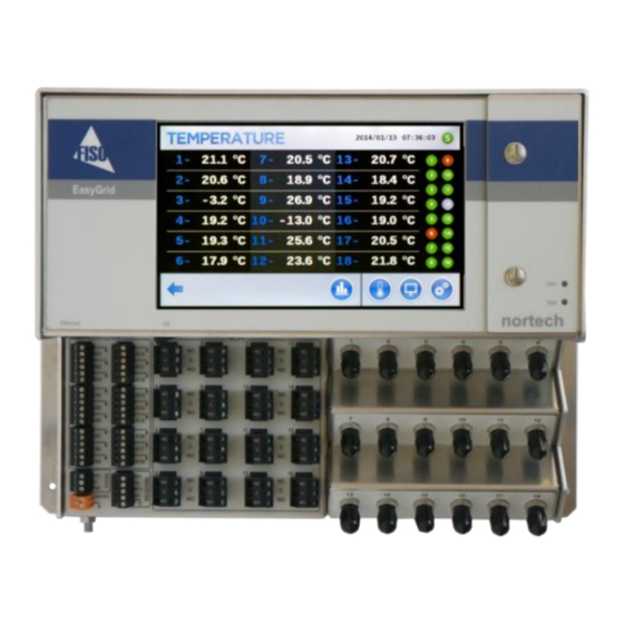
Page 27: Tft Display
EasyGrid User Guide 6.5 TFT Display The EasyGrid offers a large 17.8 cm (7”) Color touch screen. From any screen you can use the bottom navigation bar to access: Any Temperature Display Screens, Monitoring Menu or Setting Menu Information Bar located at the top of the display YYYY/MM/DD HH:MM:SS = Date and Time = System Relay Status Menu Icons... -
Page 28: System And Communication Status Led
6.7 USB Communication Port The USB communication interface is accessible in the maintenance panel. The port serves three purposes: Communicating to a PC where Nortech Client is installed to retrieve data, send data and configuration information. Upload updated version of the firmware. -
Page 29: Power Input
EasyGrid User Guide 6.8 Power Input The EasyGrid accepts 24 volts DC (±10%), 40W. WARNING To avoid damage to the unit, make sure that the power fed into the input complies with technical specifications. No other voltage level or range is accepted. Connect the unit to the power supply using terminal block connectors 24VDC and ground. -
Page 30: Analog Output
Analog outputs provide a means of transmitting temperature data directly from the unit to an external data-gathering system or monitoring equipment. The Nortech EasyGrid provides one for each temperature channel present in the unit. Wire length and gauge are related when connecting analog outputs. For a run of 100 m or less, recommended gage is 24 AWG or greater. -
Page 31: Rs-485/Rs-422 Ports
EasyGrid User Guide 6.11 RS-485/RS-422 Ports A RS-485/RS-422 serial port is provided on the EasyGrid. It can be use to connect the EasyGrid to any RS485 or RS422 communication bus. It also allows multiple EasyGrids to be link together. IMPORTANT When linking many EasyGrids on the same party line, make sure that all units have a different network ID. - Page 32 120Ω and ½ Watt. In Nortech mode, it is possible to connect up to 32 units together. When all units are connected on the same RS-485 bus, this allows a user to execute the software configuration from a single USB port.
-
Page 33: Programmable Relay Terminal Block
6.12 Programmable Relay Terminal Block All relay terminal block connectors are form-C relay interfaces. Relays 1 to 16 are programmable. The programming of the relay is done with the EasyGrid display or with the Nortech Client software. Mode Power Off Normal Cond. -
Page 34: System Relay
EasyGrid User Guide 6.13 System Relay The system relay is a form-C relay that will open or close depending on the status of the system faults. This is always configured in Fail Safe mode. Mode Power Off Normal Cond. Met Fail Safe 6.14 Protective Conductor Terminal This terminal provides an additional level of immunity against... -
Page 35: Optical Connector
EasyGrid User Guide 6.15 Optical Connector There can be up to 18 optical channels on each EasyGrid module. Each channel is designed to be connected with a TPT-62 sensor with a ST mating. Note that there can be extensions and EasyThrough between the sensor and the module. - Page 36 EasyGrid User Guide Ethernet Port (Optional) When EasyGrid is ordered with an advanced communication protocol (IEC61850, IEC60870-5-104 or DNP 3.0), the bottom plate includes an Ethernet port above the analog output terminal block. The port is dedicated to the selected communication protocol. For more information on those protocols, consult the digital communication protocol section.
-
Page 37: Monitoring
EasyGrid User Guide 7 Monitoring Values and status can be monitored from the unit TFT screen or with the Nortech Client software. On the EasyGrid display the monitoring information can be accessed at any time using the buttons. Pressing from any other screen, the user can access the last temperature page viewed and scroll through the different possible temperature views. -
Page 38: Temperature & Relay Values
EasyGrid User Guide 7.1 Temperature & Relay Values To view the measured temperature values there is 6 different options. The main difference from page to page is the number of channels that are displayed at the same time. In each page the status of all 16 possible relays is displayed on the right hand side. -
Page 39: Relay Status
EasyGrid User Guide 7.2 Relay Status This page displays the present status of each relay: Description, enable status, condition met and a graphic representation of the physical position of the relay. The “Show All” icon allows a view of all relays on a single screen. Relay Icons allow easy understanding of the relay status. -
Page 40: Temperature Statistics
EasyGrid User Guide 7.3 Temperature Statistics This page allows visualization of statistics gathered on each channel. The following information is also stored in the EasyGrid memory: Maximum Temperature Date & Time of the Maximum Minimum Temperature Date &... -
Page 41: Diagnostics
EasyGrid User Guide 7.4 Diagnostics This page allows complete diagnostic of each channel. It is important to check the light level during the installation of the system. The “Light %” is related to the strength of the light required to make an accurate reading on a sensor. A sharp increase of the light value could indicate one of the following problems: ... - Page 42 EasyGrid User Guide The “Signal %” is related to the strength of the signal required to make an accurate reading on a sensor. A sharp decrease of the signal value could indicate one of the following problems: Contaminated or Dirty connection ...
-
Page 43: General Information
EasyGrid User Guide 7.5 General Information This page gives general information about the EasyGrid system. Model Number Serial Number Embedded Software Version Number of Temperature Channels Number of Programmable Relays EasyGrid Internal Temperature HTML Software Version ... -
Page 44: Transformer Information
EasyGrid User Guide 7.6 Transformer Information This displays general information about the transformer. Three fields are available to provide the end-users with information about the transformer: Name, Type and Description. -
Page 45: Settings
EasyGrid User Guide 8 Settings All parameters can be modified from the unit TFT screen or from the supplied Nortech Client application. On the EasyGrid display, the configuration menu can be accessed at all time using the button. Pressing brings the setting menu page from where you can select between 8 categories: ... -
Page 46: Temperature Parameters
EasyGrid User Guide 8.1 Temperature Parameters This page allows parameter customization associated to any channel. Enable Description Allows activation of a channel. Click on Icon to Enable or Disable a channel. Range Enable: Channel is activated. Disable: Channel is deactivated. The channel is not scanned. - Page 47 EasyGrid User Guide Offset Description Applies an offset to the temperature being read by the unit. Click on the field to change the offset. Range -40°C to 225°C Set All Description Allows activation of one, multiple or all channels at the same time. Click on Icon to Enable or Disable a channel.
-
Page 48: Relay Settings
EasyGrid User Guide 8.2 Relay Settings Each relay must be programmed separately. This section explains the different parameters and their functionality. Description Description Associates a description to the relay. Range Any string of characters (max 18 characters). Function Description Allows the relay logic to be activated. Range Enable: Relay is activated. - Page 49 EasyGrid User Guide Operation Description Select relay position when the conditions are not met. Range Normal: When conditions are not met the relay is in the Normally-Closed position. Fail Safe: When conditions are not met the relay is in the Normally-Open position. Mode Power Off Normal...
- Page 50 EasyGrid User Guide Offset Description Sets seasonal offset values applies an offset to the relay Setpoint for the selected period. For example, Setpoint may be increased by 5°C for the summer period. This function is inactive when the offset is 0°C. Range Resulting range: -40°C to 225°C Channels List...
- Page 51 EasyGrid User Guide Hysteresis Description Sets the hysteresis values to exit the condition met status. Range -40°C to 225°C Logic Description Selects the logic used to control the relay. Range OR: Condition is met when ANY of the selected channels are ABOVE the Setpoint. AND: Condition is met when ALL of the selected channels are ABOVE the Setpoint.
- Page 52 EasyGrid User Guide Activation Delay Description Sets a delay between the conditions met time and the relay operation. Range 0 to 60 minutes The graphic below helps understanding the concepts of Hysteresis and Activation delay. Activation Delay = 0 min. Activation Delay >...
- Page 53 EasyGrid User Guide Exerciser Function Description Enable or Disable this function. Range Enable: Exerciser function is active Disable: Exerciser function is inactive Exerciser Duration Description Selects duration time of the exercising session. Range 1 to 60 minutes Exerciser Cycle Description Sets the number of days between exercising sessions.
-
Page 54: Advanced Config
EasyGrid User Guide 8.2.1 Advanced Config The “Advanced Configuration” button at the bottom of the page allows configuration of the period. It is important to know that the season period will be the SAME for all relays. Start Month Description Defines the first month of the period * Same for ALL relays. - Page 55 EasyGrid User Guide End Month Description Defines the last month of the period * Same for ALL relays. Range 1 to 12 (January to December) End Day Description Defines the last day of the period * Same for ALL relays Range 1 to 31 Test...
-
Page 56: Statistics Reset
EasyGrid User Guide 8.3 Statistics Reset This page allows you to reset statistics associated to a single channel or for all channels at the same time. Reset for Channel #1 Reset for All Channels Reset Description Resets the statistics per channel. Reset All Description Resets the statistics for all channels. -
Page 57: Analog Outputs
EasyGrid User Guide 8.4 Analog Outputs This page allows you to customize the analog output scale. For each channel you will find 5 parameters. Set Min T° Description Temperature value at a 4mA output. Range -40°C to 225°C Set Max T° Description Temperature value at a 20mA output. - Page 58 EasyGrid User Guide Reset All Description Resets all analog outputs to default values. Min T° = -40.0°C Max T° = 225.0°C Set All Description Sets all analog outputs to the same values for Min T° and Max T°...
- Page 59 EasyGrid User Guide Here are the formulas for the Analog Output. The Analog Output is represented by a straight line equation of this form: Parameter Symbol Formula Set Min T° AnaOutMin °C Set Max T° AnaOutMax °C °C / mA I (mA) T°...
-
Page 60: Display Settings
EasyGrid User Guide 8.5 Display Settings This page gives access to the parameters related to the EasyGrid display T° Unit Description Select Temperature unit Range °C : Celsius °F : Fahrenheit Scroll Description Speed of the Auto-Scroll function Range Fast: every 1 second Medium: every 2 seconds Slow: every 4 seconds... - Page 61 EasyGrid User Guide Default Description Default temperature page after the unit power up Range Any of the 6 temperature pages. Display Calibration Description Runs touch screen calibration, returns to Display Settings page when calibration completed. Range Screen Saver Description Time before the screen saver kicks in. If set to NEVER there is no screen saver.
-
Page 62: Data Logging
EasyGrid User Guide 8.6 Data Logging This page allows the configuration of parameters for the data logging function. The data logger can record the following information during each period: Present Temperature for each channel Maximum Temperature for each channel ... - Page 63 EasyGrid User Guide Logging Period Description Time between each log. Important: Apply button must be press to confirm the changes. Range 1 second to 30 days Logging Status Description Enable or Disable the data logging function by using the Start and Stop button. Range Running: Data is logged for the defined period.
- Page 64 EasyGrid User Guide Memory Used Description Internal memory currently used in percentage. The memory is emptied by pressing the Clear button. Range 0% to 100% Memory Card Capacity Description Total capacity of the memory card inserted in the unit in GB. Range >...
- Page 65 EasyGrid User Guide Memory Card Used Description Amount of data written in the memory card in GB Range ≥ 0.00GB Sync In Progress Description Indicates when the unit is writing on the memory card. The synchronization can be forced by pressing the Sync button.
-
Page 66: General Settings
EasyGrid User Guide 8.7 General Settings This page allows modification of general parameters. Date / Time Description Date and Time for the EasyGrid Real Time Clock. Important: Apply button must be press to confirm the changes. Range Any day or Time... - Page 67 EasyGrid User Guide System Relay Description System Relay current status. Note: the system relay operation mode is ALWAYS Fail Safe. Range Not Applicable Password Protection Description Allows the User to Enable or Disable the password protection for the setting section. Range Password length is 4 Factory Setting...
- Page 68 EasyGrid User Guide Transformer Name Description Variable to store the transformer name. Range Any string of characters Maximum length is 18 Transformer Type Description Variable to store the transformer type. Range Any string of characters Maximum length is 18 Transformer Description Description Variable to store the transformer description.
-
Page 69: Communication
EasyGrid User Guide 8.8 Communication This page is dedicated for setting communication parameters. Nortech Modbus Rtu Modbus Ascii IEC 61850 IEC 60870-5-104 Modbus TCP-IP DNP 3.0 Users can select one of the 7 COM configurations: Nortech MODBUS RTU ... - Page 70 EasyGrid User Guide Appropriate parameters according to selected protocol will be requested Nortech Address Description Current Nortech Address for Nortech protocol. Range 1 to 32 Modbus Address Description Current Modbus Address for the Other protocols than Nortech. Range 1 to 247...
- Page 71 EasyGrid User Guide Parity Description Communication Parity for Modbus RTU and Modbus Ascii. Range None Even Character Interval Description Communication Character Interval in millisecond (ms) for Modbus Ascii. Range 5 to 100 End of Frame Character Description Communication End Of Frame Character (EOF) for Modbus Ascii.
-
Page 72: Nortech Client Software
EasyGrid User Guide 9 Nortech Client Software The Nortech Client software is used to configure the Nortech EasyGrid system and retrieve all the data stored in the unit. It is possible to communicate directly through the USB interface of the Nortech EasyGrid unit from your office PC. -
Page 73: Main Window
EasyGrid User Guide 9.2 Main Window FOR DETAILED INFORMATION PLEASE CONSULT THE NORTECH CLIENT SOFTWARE Information Tabs Toolbar Menu Bar Device List Selected Device Info Tabs Specific Area The Menu Bar and Toolbar give quick access to serial port connection, network configuration, firmware update, and view options. -
Page 74: Connecting To The Easygrid
EasyGrid User Guide 9.3 Connecting to the EasyGrid 1. Unlock both screws and open the maintenance door, connect a USB cable to the USB port. Connect the other end of the USB cable to the PC. On the first connection, Windows might need to download and install the FTDI USB driver which is available on windows update. -
Page 75: Firmware Update
EasyGrid User Guide 9.4 Firmware Update With the appropriate firmware file, the EasyGrid unit can be updated using the Nortech Client application. To open the firmware update window, select the Firmware Update button in the toolbar or in the Tools menu. -
Page 76: Digital Communication Protocol
If you intend to connect multiple units to a RS-485 bus, a unique network address must be set to each unit before installation. Otherwise, you will have to go to each unit location with a portable computer and configure its network address on-site. The Nortech network address is configured through the Nortech Client software. -
Page 77: Modbus
Modbus protocol. The Nortech EasyGrid unit can be setup to communicate on standard Modbus networks using either of two transmission modes: ASCII or RTU. Users select the desired mode, along with the serial port communication parameters (baud rate, parity mode, etc.), during configuration of each controller. -
Page 78: Communication Configuration
EasyGrid User Guide 10.2.1 Communication Configuration Your configuration for communication protocol should be set to “Modbus RTU”, “Modbus ASCII” or “Modbus TCP-IP”. Communication Mode ASCII Network Address 1 to 247 Bits / Word Data Bits Parity None = 2 Stop Bits Even = 1 Stop Bit Stop Bits Odd = 1 Stop Bit... -
Page 79: Supported Functions
EasyGrid User Guide 10.2.2 Supported Functions Function Code Data Type Access Description (decimal) Read Coils Read Only Read one or more Coil Input(s) Read Discrete Inputs Read Only Read one or more Discrete Input(s) Read Holding Registers Read Only Read one or more Holding Register(s) Read Input Registers Read Only Read one or more Input Register(s) -
Page 80: Modbus Register Map
10.2.4 Modbus Register map The following tables contain the Modbus register mapping used in the Nortech EasyGrid: Note: For Channel, Alarm and Relay the maximum count is up to 32 but in fact you will be able to send commands up to the number of Channels, Alarms and Relays available on your device. - Page 81 Com Nortech Address 1 to 32 16385 16385 UInt16 Com Nortech Baudrate 115 200 (Scale : x100) 16386 16386 UInt16 Com Nortech Data Bits 0 – None 16387 16387 UInt16 Com Nortech Parity 16388 16388 UInt16 Com Nortech Stop Bits...
- Page 82 EasyGrid User Guide Data Type : Read Holding Registers and Read Inputs Registers (Int32 and UInt32) Address Data Data Name Value Size Format Count Start 20480 20481 UInt32 Log Event Count 0 to 24576 20482 20483 UInt32 Log Event Size 24576 20484 20485 Log Mega Count...
- Page 83 EasyGrid User Guide Data Type : Read Holding Registers and Read Inputs Registers (String) Address Data Data Name Value Size Format Count Start “NA” 4096 4703 String Alarm Description “NA” 12768 13375 String Channel Description “SEN-XX-#” 32780 32791 String System Model “00000000”...
-
Page 84: Modbus Message Description
EasyGrid User Guide 10.2.5 Modbus Message Description General Official reference documents are available at www.modbus.org MODBUS Protocol Specification MODBUS Over Serial Line FOR LEGACY APPLICATIONS ONLY Request Type Start Slave Address Function Code Data Checksum Type Address Function Data “\r\n” ASCII Address Function... - Page 85 EasyGrid User Guide Read Discrete Inputs Request Size Value Function Code 1 Byte 0x02 Starting Address 2 Bytes 0x0000 to 0xFFFF Quantity of Inputs 2 Bytes 0x0000 to 0x07D0 (1 to 2000) Response Size Value Function Code 1 Byte 0x02 Byte Count 1 Byte Input Status...
- Page 86 EasyGrid User Guide Read Input Registers Format Request Size Value Function Code 1 Byte 0x04 Starting Address 2 Bytes 0x0000 to 0xFFFF Quantity of Input Registers 2 Bytes 0x0001 to 0x007D (1 to 125) Response Size Value Function Code 1 Byte 0x04 Byte Count 1 Byte...
-
Page 87: Modbus Example
EasyGrid User Guide 10.2.6 Modbus Example Read Coils for Relay 1 to 6 TX >> 01 01 6000 0006 A208 RX << 01 01 01 05 918B TX >> : 01 01 6000 0006 98 \r\n ASCII RX << : 01 01 01 05 F8 \r\n relay 1 : 1 ->... -
Page 88: Ethernet Protocol Configuration
To change your IP address you will need a Windows base PC on the same network and also the software “IP Finder” provided by us. This software can be found into the Nortech Client installation folder. By default this folder is: “C:\Program Files\FISO Technologies\Nortech Client”... - Page 89 EasyGrid User Guide Run the IP Finder software. At the start-up the IP Finder will launch automatically a scan onto the network to find your EasyGrid. If you want to scan again just click on Refresh List. After the scan you should see your EasyGrid into the list, if not verify that your Firewall on your Windows base PC is deactivated.
- Page 90 EasyGrid User Guide After you have applied your setting, you will need to reboot your EasyGrid. So click on “Reboot Device” and in the “Reboot Device” dialog box enter again the password “Netsilicon” and click on “Reboot”. The status should be “Rebooting”. Wait for about 60 seconds and the status should be “Ready”. Now you can close this dialog box by clicking on “Close”.
-
Page 91: Iec 61850
EasyGrid User Guide 10.4 IEC 61850 Your configuration for communication protocol should be set to “IEC 61850”. Note: For Channel, Alarm and Relay the maximum count is up to 32 but in fact you will be able to send commands up to the number of Channels, Alarms and Relays available on your device. <x>... -
Page 92: Iec 60870-5-104
EasyGrid User Guide 10.5 IEC 60870-5-104 Your configuration for communication protocol should be set to “IEC 60870-5-104”. Note: For Channel, Alarm and Relay the maximum count is up to 32 but in fact you will be able to send commands up to the number of Channels, Alarms and Relays available on your device. IEC60870-5-104 Address Data... -
Page 93: Dnp 3.0
EasyGrid User Guide 10.6 DNP 3.0 Your configuration for communicate on protocol should be set to “DNP 3.0”. Note: For Channel, Alarm and Relay the maximum count is up to 32 but in fact you will be able to send commands up to the number of Channels, Alarms and Relays available on your device. -
Page 94: System Installation
EasyGrid User Guide 11 System Installation 11.1 General The sensor installation phase should be thoroughly planned before proceeding. Good planning for this phase means determining the following beforehand: Where the sensors will be installed. How the sensor tips will be held in place. How the sensor cabling will be routed out of the winding. -
Page 95: Handling Optical Cable
EasyGrid User Guide IMPORTANT When installing sensors in the windings, it is recommended not to take up more than 10% of the coil surface. In general, it is preferable to install sensors as far along the manufacturing process as possible in order to minimize handling. - Page 96 EasyGrid User Guide Keep connectors Clean A dirty connector will attenuate or stop the light signal from reaching the sensor. Keep the connections clean using the procedure in the Maintenance Section of this manual. Keep the connector free of nicks, burrs or scratches When the surface of a connector is damaged the only way to repair it is to polish it.
-
Page 97: Assembly Diagram
EasyGrid User Guide 11.3 Assembly Diagram... -
Page 98: Sensor Installation
EasyGrid User Guide 11.4 Sensor Installation 11.4.1 Winding Spacer with Easy Disk FISO strongly recommends the use of the EasyDisk for the installation of a TPT-62 sensor inside a winding spacer. Additionally to the following steps, a video that shows an EasyDisk installation is available. - Page 99 EasyGrid User Guide 11.4.1.2 Pre Drilling 11.4.1.3 Using the Knockout Punch...
- Page 100 EasyGrid User Guide 11.4.1.4 Cutting the Cable Slot 11.4.1.5 Inserting the Easy Disk...
-
Page 101: Sensor Handling Until Routing
EasyGrid User Guide 11.5 Sensor Handling until Routing The sensors are typically quite long (from 3m up to 15m) and it is advisable to coil as much of the sensor as possible in loops no smaller than 15 cm for ease of handling. The coil can be attached with cotton strapping or string (do not use nylon cord, as over tightening it can break the fiber). -
Page 102: Probe Routing
EasyGrid User Guide 11.7 Probe Routing Assuming the sensor exits the winding along the winding leads, the sensors can all run along the top of the windings to one wall of the tank. Note that this routing should be done only after the winding and core assembly have been installed in the tank, the idea again being to keep as many sensor installation steps as possible until a maximum of the other fabrication steps have been done. -
Page 103: Tank Wall Assembly Installation
EasyGrid User Guide 11.8 Tank Wall Assembly Installation The EasyThrough is installed on the tank wall of the transformer and, once the core and windings have been installed in the tank, the sensors are routed and connected to the EasyThrough. Successful installation requires both careful planning prior to installation and thorough understanding of certain basic properties of fiber optic sensors by all employees expected to handle the sensors or the windings once the sensors have been installed. -
Page 104: External Optical Extension Installation
EasyThrough connectors and the EasyGrid. The total length of the sensor cable plus the extension cable can be up to 1000 m due to the tremendous dynamic range of the Nortech EasyGrid. This allows installation of the electronics at the most advantageous location. -
Page 105: Troubleshooting
EasyGrid User Guide 12 Troubleshooting 12.1 Solving Common Problems The following troubleshooting guide was designed to help you solve technical problems. If you conclude that the unit has to be returned for repair, or if you need assistance, please contact FISO Customer Support. -
Page 106: Resetting To Factory Defaults
EasyGrid User Guide The temperature value is replaced by an Error Code when there is something wrong with the channel. The error appears on a temperature channel in the different measurement pages. EasyGrid Error Possible Cause Possible Solution Displays Description Measured temperature is Make sure minimum sensor Signal Too Low... -
Page 107: Cleaning Procedure
Read carefully the below instruction before using the device. Important The One-Click cleaner is designed to clean Nortech fiber optic connectors. FISO is not liable for any damage caused in attempts to apply this device to other applications. -
Page 108: Cleaning The Male St Connector
EasyGrid User Guide 13.1.2 Cleaning the Male ST Connector Step 1: Open the end-cover on the Guide Cap Step 2: Insert the Connector Ferule into the Guide Cap Step 3: Push the Outer Shell to Clean the Connector Face Step 4: Turn the Cleaner body by 90° Step 5: Push the Outer Shell to Clean the Connector Face for a second time... -
Page 109: Cleaning The St Mating
EasyGrid User Guide 13.1.3 Cleaning the ST Mating Step 1: Remove the Guide Cap from the Device Step: 2 Step: 3 Step: 4 Step: 5 Insert the cleaner tip in Push the outer shell to Turn the cleaner body by Push the outer shell a the mating. -
Page 110: Gallium Arsenide Principle
EasyGrid User Guide 14 Gallium Arsenide Principle 14.1 Gallium Arsenide Theory 14.1.1 The Principle FISO’s fiber-optic temperature sensors, for high voltage temperature measurement, are based on white light absorption/transmission by a GaAs (gallium arsenide) semiconductor. The effects of temperature variations on this semiconductor are well known and predictable. As the temperature of the semiconductor increases, the semiconductor’s transmission spectrum (i.e. -
Page 111: The Temperature Sensor
EasyGrid User Guide 14.1.2 The Temperature Sensor The TPT-62 sensor is based on direct contact temperature measurement. Traditional temperature sensors like thermocouples and RTDs (resistance temperature devices) work on the same principle. In other words, the semiconducting material must be touching the object or immersed in the liquid or gas to be measured. -
Page 112: Warranty
EasyGrid User Guide 15 Warranty 15.1 General Information FISO (FISO) warrants this equipment against defects in material and workmanship for a period of four years and its fiber optic transducers and sensors for ninety (90) days from the date of original shipment. FISO also warrants that this equipment will meet applicable specifications under normal use. -
Page 113: Service And Repairs
EasyGrid User Guide 15.5 Service and Repairs FISO commits to providing product service and repair on the fiber optic monitors. To send any equipment for service or repair: Call FISO’s authorized service centers Support personnel will determine if the equipment requires service, repair, or calibration. -
Page 114: Transportation
EasyGrid User Guide 15.6 Transportation Maintain a temperature range within specifications when transporting the unit. Transportation damage can occur from improper handling. The following steps are recommended to minimize the possibility of damage: Pack the unit in its original packing material when shipping. Avoid high humidity or large temperature fluctuations.
Need help?
Do you have a question about the EasyGrid V1 and is the answer not in the manual?
Questions and answers