Advertisement
Quick Links
mLINE
PROCESS CONTROL UNITS
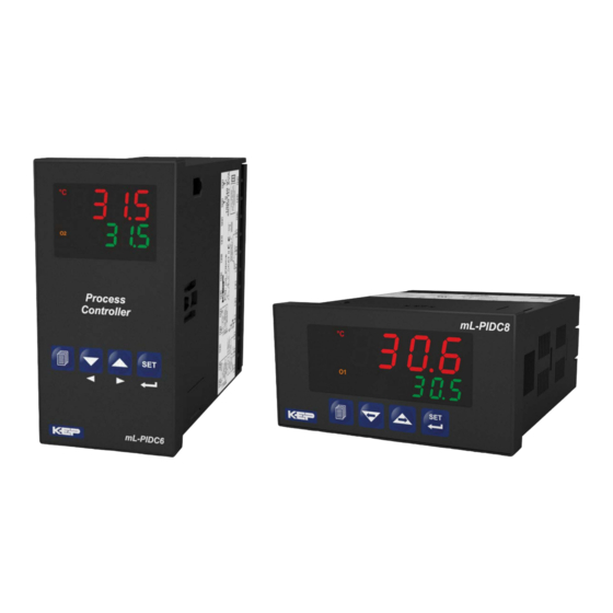
mL-PIDC6 & mL-PIDC8
mL-PIDC6 & mL-PIDC8 Universal Input PID Process
Controllers
-
4 digits process (PV) and 4 digits process set (SV) display
- Universal process input(TC, RTD, mV Z, V Z
- Optional secondary sensor input
- Dual or multi point calibration for
-
Configurable ON/OFF, P, PI, PD and PID control forms
- Auto-tune and Self-tune PID
- Manual/Automatic mode selection for control outputs
- Bumpless transfer
- Motorized valve control function
- Programmable heating, cooling and alarm functions for control
outputs
- 8 steps profile control ( Ramp & Soak ) function and start-hold stop by
using logic input module
- Remote set point function by using analog input modules
- Re-Transmission
-
Detection of heater failure by using 0...5 AVCT input module
-
RS-485 serial communication with Modbus RTU protocol
SPECIFICATIONS:
Process Inputs
Universal Input:
Universal input, TC, RTD,
Thermocouple
(TC) : L(DIN 43710) ,J , K , R , S , T , B , E ve N
(IEC584.1)(ITS90) ,C (ITS90)
Thermoresistance
(RTD): PT-100 (IEC751)(ITS90)
Z
Input
: mV, V, mA
Measurement Range:
Please refer to Table-1 for selection of input
type and scale.
Accuracy:
± 0,25% of full scale for thermocouple, thermoresistance
and voltage
Cold Junction Compensation
Line Compensation
:
Maximum 10 Ohm
Sensor Break Protection:
Upscale
Sampling Cycle
:
3 samples per second
Input Filter :
0.0 to 900.0 seconds
CONTROL
Control Forms:
Programmable ON / OFF, P, PI, PD or PID.
OUTPUT
Standard Relay Output
: 5A@250V
alarm output) (Electrical Life : 100.000 Operation (Full Load))
Extra Relay Output
-
V
3A@250V
Relay Output
ADDITIONAL INPUT
Extra Analog Input
-0/4...20 mA
Z
Current Input
Supply Voltage
100-240V
V
50/60 Hz (-%15;+%10) -6VA
, mA
Z)
Z
Z
voltage &
Current input
Voltage/Current
Z
:
Automatically ± 0.1°C/1°C.
V
(Programmable control or
INDICATORS
Process Indicators :
mL-PIDC6 : 10.1 mm Red 4 digit LED Display
mL-PIDC8 : 13.2 mm Red 4 digit LED Display
Setpoint Indicators :
mL-PIDC6 & mL-PIDC8 : 8 mm Green 4 digit LED Display
LED Indicators : AT(Auto Tuning), SV(Set Value), Man(Manual
Operation),Auto(Auto Operation), O1/2/3 (Output status LEDs),°C,°F,
V, Ramp and Remote LEDs
Environmental Ratings and Physical Specifications
Operating Temperature:
0...50°C
Max. Operating Humidity
:
0-90%RH
Protection Class NEMA 4X (IP65 at front, IP20 at rear).
:
Mounting:
Type-1 Enclosure Mounting
Installation:
Fixed installation Category II
Over Voltage Category:
II
Pollution Degree:
II, office or workplace, none conductive pollution
Weight:
mL-PICD6 & mL-PIDC8 : 260 gr.
Dimensions / Panel Cut-Out:
mL-PIDC6 : (48 x 96mm, Depth: 86.5 mm) / (46 x 92mm)
mL-PIDC8 : (96 x 48mm, Depth: 86.5 mm) / (92 x 46mm)
Minimum Distance Between Panel Cut-Out Centers:
mL-PIDC6 : X=65mm, Y=129mm
mL-PIDC8 : X=129mm, Y=65mm
Electrical Connections
Universal
Process Input
(TC, RTD, Voltage/Current)
Sensor or Transmitter
Supply Voltage
Z
0 to 50mV
Z
0 to 10V
0 to 20mA Z
Pt-100
TC
1
2
3
4
5
6
MODULE - 1
MODULE - 2
13
14
15
16
17
18
Additional
Additional Relay
0/4-20mA
Form A
Input
3A@250V
(non-condensing)
Output-3
Standard Relay Output
7
8
9
10
11
12
NC
NO
C
OUTPUT - 3
5A@250V V
c
Y
CAT II
a
19
20
21
22
23
24
Supply Voltage Input
100-240VAC (-15%;+10%)
50/60Hz - 6VA
991036 08/13/19
Advertisement

Summary of Contents for KEP m Series
- Page 1 mLINE INDICATORS PROCESS CONTROL UNITS Process Indicators : mL-PIDC6 & mL-PIDC8 mL-PIDC6 : 10.1 mm Red 4 digit LED Display mL-PIDC8 : 13.2 mm Red 4 digit LED Display Setpoint Indicators : mL-PIDC6 & mL-PIDC8 : 8 mm Green 4 digit LED Display LED Indicators : AT(Auto Tuning), SV(Set Value), Man(Manual Operation),Auto(Auto Operation), O1/2/3 (Output status LEDs),°C,°F, V, Ramp and Remote LEDs...
-
Page 2: Panel Mounting
DIMENSIONS mL-PIDC6 Cut Out mL-PIDC8 °C REMOTE °F RAMP Cut Out AUTO PANEL MOUNTING Before mounting the device in your panel, make sure that the cut-out is of the right size. Check front panel gasket position 3-Insert the device through the cutout. -
Page 3: Motorized Valve Control
Adjustment of Process Set Value Main Operation Process Set Display °C °C °C °C °F °F °F °F REMOTE RAMP AUTO REMOTE RAMP AUTO REMOTE RAMP AUTO REMOTE RAMP AUTO Press menu Change set value with Press SET/OK button to accept button increment and the new Set value. - Page 4 While passing from manual control to automatic control, last process Defines type and scale of the thermocouple for TC input. It output value in manual control is accepted as first process output value in is active if TC input type is selected automatic control and automatic control continues to run.
- Page 5 MAXIMUM CONTROL OUTPUT ( , 100.0)% Process Even as a result of the PID calculation device calculates the % Set value output value greater than this parameter, heating or cooling output is active maximum for OUL parameter. Po10 Po11 Po09 HEATING MINIMUM CONTROL OUTPUT TIME(0.0, )sec...
- Page 6 PROCESS VALUE STABILIZATION ýoP1 ConF:MODULE-1 Configuration Parameters (1, SCALE HIGH POINT)Unit These devices are equipped with a 0/4 to 20 mA analog It is used for controlling if process value oscillates or not input plugged into Module-1 when Parameter is <= Process Value <= Configuration of analog input module in Module-1socket.
- Page 7 out3 ConF: Output-3 Configuration Parameters ýoP1 ConF: MODULE-2 Configuration Parameters These devices are equipped with an additional Relay Defines output function for Output-3 Output plugged into Module-2 socket. Heating Cooling out 2 Defines output function for Module-2 Logic output Heating Defines control algorithm of Output-3.
- Page 8 Alarm Types Alarm Types Deviation high alarm Process high alarm Alarm Output Process Alarm Process Set + Alarm Set Output Alarm Process Value Deviation low alarm Process Value Alarm Process low alarm Output Process Set Process Set - Alarm Set Alarm Output Alarm...
- Page 9 Parity Selection for Communication If top display blinks : If analogue input °C No parity. value is less than minimum value of °F operating scale top display starts to Odd parity. blink. Even parity. Stop Bit Selection for Communication REMOTE RAMP AUTO 1 stop bit...
- Page 10 Fax: 732-935-9344 info@kep.com Email: Web: www.kep.com • www.kepmline.com This symbol is used for safety warnings. User must pay attention to these warnings. This symbol is used to determine the dangerous situations as a result of an electric shock. User must pay attention to these warnings definitely.
Need help?
Do you have a question about the m Series and is the answer not in the manual?
Questions and answers