Table of Contents
Advertisement
Quick Links
Advertisement
Table of Contents

Related Manuals for Sentera Controls FCMF R Series


Summary of Contents for Sentera Controls FCMF R Series
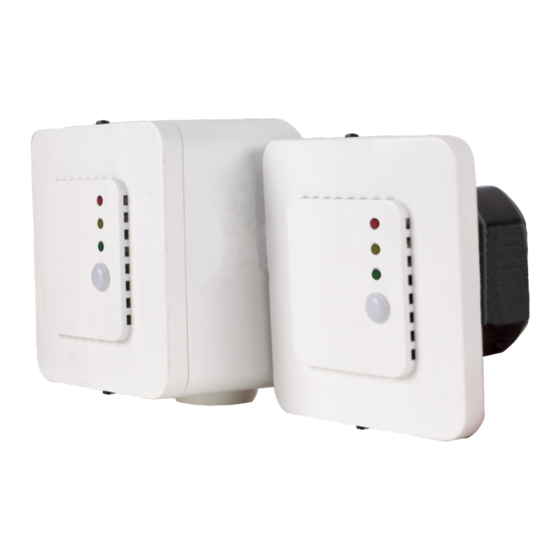
- Page 1 FCMFX-R INTELLIGENT CO SENSOR Mounting and operating instructions...
-
Page 2: Table Of Contents
FCMFX-R INTELLIGENT CO SENSOR Table of contents SAFETY AND PRECAUTIONS PRODUCT DESCRIPTION ARTICLE CODE INTENDED AREA OF USE TECHNICAL DATA STANDARDS OPERATIONAL DIAGRAMS WIRING AND CONNECTIONS MOUNTING INSTRUCTIONS IN STEPS OPERATING INSTRUCTIONS VERIFICATION OF INSTALLATION TRANSPORT AND STORAGE WARRANTY AND RESTRICTIONS MAINTENANCE MIW-FCMFX-R-EN-000 - 29 / 05 / 2021 2 - 10... -
Page 3: Safety And Precautions
FCMFX-R INTELLIGENT CO SENSOR SAFETY AND PRECAUTIONS Read all the information, the datasheet, Modbus map, mounting and operating instructions and study the wiring and connection diagram before working with the product. For personal and equipment safety, and for optimum product performance, make sure you entirely understand the contents before installing, using or maintaining this product. -
Page 4: Product Description
FCMFX-R INTELLIGENT CO SENSOR PRODUCT DESCRIPTION The FCMFX-R series are intelligent sensors featuring adjustable temperature, relative humidity and CO ranges. The used algorithm controls a single analogue / modulating output based on the measured T, rH and CO values, which can be used to directly control an EC fan, an AC fan speed controller or an actuator powered damper. -
Page 5: Operational Diagrams
FCMFX-R INTELLIGENT CO SENSOR Part 1: General requirements ■ EMC Directive 2014/30/EC: ► EN 60730-1:2011 Automatic electrical controls for household and similar use - Part 1: General requirements ► EN 61000-6-1:2007 Electromagnetic compatibility (EMC) - Part 6-1: Generic standards - Immunity for residential, commercial and light industrial environments ►... -
Page 6: Wiring And Connections
FCMFX-R INTELLIGENT CO SENSOR LED indications - T, rH or CO (default) WIRING AND CONNECTIONS Article type FCMFF-R FCMFG-R 18—34 VDC 18—34 VDC 15—24 VAC ±10% Common Ground AC ~ ground Modbus RTU (RS485), signal A Modbus RTU (RS485), signal /B Analogue / modulating output (0—10 VDC / 0—20 mA / PWM) Ground AO... - Page 7 FCMFX-R INTELLIGENT CO SENSOR that it can be easily connected. Do the wiring according to the wiring diagram (see Fig. 1). Fig. 1 Wiring and connections Modbus Supply voltage: FCMFF-R: 18—34 VDC FCMFG-R: 18—34 VDC / 15—24 VAC ±10 % Analogue / modulating output Mount the internal enclosure into the wall using appropriate connecting elements...
- Page 8 FCMFX-R INTELLIGENT CO SENSOR Insert the connecting cables through the grommets of the unit. Fig. 4 Mounting dimensions - surface mounting Fig. 5 Mounting position Correct Incorrect Position at min. 1,5 m from the floor Do the wiring according to the wiring diagram (see Fig. 1) using the information from section “Wiring and connections”.
-
Page 9: Operating Instructions
FCMFX-R INTELLIGENT CO SENSOR ATTENTION Do not expose to direct sunlight! OPERATING INSTRUCTIONS ATTENTION The unit is supplied with electrical energy at voltages high enough to inflict personal injury or threat to health. Calibration procedure: Sensor calibration is not necessary. All sensor elements are calibrated and tested in our factory. -
Page 10: Verification Of Installation
FCMFX-R INTELLIGENT CO SENSOR The intensity of the LEDs can be adjusted between 0 and 100 % with a step of 10 NO T E % according to the value set in Holding register 80. Writing “0” in Holding register 80 turns OFF all LEDs.
Need help?
Do you have a question about the FCMF R Series and is the answer not in the manual?
Questions and answers