Advertisement
Quick Links
Advertisement

Subscribe to Our Youtube Channel
Summary of Contents for DISCOBED 19890
- Page 1 Assembly Instructions Mobiles Pflegebett Montageanleitung discobed.de AI19890DE...
- Page 2 IMPORTANT INFORMATION CONCERNING THIS PRODUCT TO PREVENT SERIOUS OR FATAL INJURIES Keep these instructions for future reference 1. Read carefully and fully understand the manufacturer’s assembly. 2. Care and special attention should be used where a warning is indicated. 3. DO NOT use substitute parts. Contact the manufacturer or dealer for replacement parts. 4.
- Page 3 PARTS TEILE 2x wrench 2x Schraubenschlüssel 2x hex wrench Foot End frame Head End frame 2x Sechskantschlüssel Rahmen Fußende Rahmen Kopfende 4x disc pins 4 x Stift mit Backrest Sicherungskette Rückenlehne Head Straight Rail, Side A, Head Straight Rail, Side B Seitenstange Kopfende, Seite A Seitenstange Kopfende, Seite B Pneumatic Strut...
- Page 4 STEP 1. PREPARE PARTS FOR ASSEMBLY SCHRITT 1. VORBEREITUNG DER MONTAGE 1.1. Remove the discs from each of the bed end frames and set to the side for later use. 1.2 Lay out the head and foot end frames about 6 ft. apart from one another. 1.1 Nehmen Sie die Discs aus den Rahmenstücken heraus und legen Sie sie beiseite für später.
- Page 5 STEP 2. CONNECTING SWAGED SIDE RAILS TO STRAIGHT SIDE RAILS SCHRITT 2. VERBINDEN DER GERADEN UND GESTAUCHTEN SEITENSTANGEN 2.1 Attach head swaged side rail A to straight rail A. 2.1 Verbinden Sie die gestauchte Seitenstange des Kopfendes Seite A mit der geraden Seitenstange A. 2.2 Attach foot swaged side rail A to straight rail A.
- Page 6 STEP 3. SECURING DISC TO ASSEMBLED SIDE RAILS SCHRITT 3. DIE DISCS AN DEN MONTIERTEN SEITENSTANGEN FIXIEREN 3.1 Holding the head swaged rail A, press pin A down and hold. 3.2 Line up pin with hole in disc, insert into disc. Let pin go. 3.1 Halten Sie die gestauchte Seitenstange des Kopfendes Seite A, drücken Sie den Pin (A) herunter und halten ihn gedrückt.
- Page 7 STEP 4. SECURING EACH DISC TO THE HEAD END FRAME SCHRITT 4. DIE DISCS IM RAHMEN DES KOPFENDES SICHERN 4.1 Make sure the hole in the disc is lined up with the hole in the head end frame side A (see diagram) 4.2 Loosely place the disc into the loop of the bed head end frame A, ensure your fingers are not in the way and firmly push down on the side rail (see diagram) 4.3 Make sure the disc fits completely into the bed head end frame (see diagram)
- Page 8 STEP 5. INSTALL BACK REST SUPPORT BAR SCHRITT 5. DIE RÜCKENLEHNENSTÜTZSTANGE MONTIEREN 5.1 Line up the back rest support bar, and slide through each hole on the head swaged rail support rails. 5.2 Using bolt and wing nut, hand tighten 5.1 Nehmen Sie die Rückenlehnenstützstange und schieben Sie sie durch die Öffnungen an den Stützpunkten der Seitenstangen am Kopfende.
- Page 9 STEP 6. ATTACHING SLEEPING MAT TO SIDE RAILS SCHRITT 6. DIE MATTE AUF DIE SEITENSTANGEN AUFZIEHEN 6.1 Open out the sleeping mat with the correct (logo) side up. 6.2 Starting at the foot end, feed the side sleeves over the side rails and slide mat up toward the head bed end frame until it reaches the head adjustable section.
- Page 10 STEP 8. SECURING EACH DISC TO THE FOOT END FRAME SCHRITT 8. DIE DISCS IM RAHMEN DES FUSSENDES SICHERN 8.1 Make sure the hole in the disc is lined up with the hole in the foot end frame side A. 8.2 Loosely place the disc into the loop of the bed foot end frame A, ensure your fingers are not in the way and firmly push down on the side rail.
- Page 11 STEP 9. SETTING UP BACKREST SCHRITT 9. DIE RÜCKENLEHNE MONTIEREN 9.1 Insert back rest into backrest sleeve. 9.1 Führen Sie die Rückenlehne in die dafür vorgesehene Öffnung der Matte ein. 9.2 Making sure that the support frames from the rails are through the loop, connect backrest to hinge of side rails. Click into place.
- Page 12 STEP 10. CONNECTING STABALIZER BRACKETS SCHRITT 10. VERBINDEN DER SEITENSTABILISATOREN 10.1 Line up stabilizer bar with the attachement points to the leg of the head end frame, and to the side rail on side A. 10.2 Loosely attach the bolts by hand for side A. 10.3 Repeat step 10.1 and 10.2 on side B.
- Page 13 STEP 11. CONNECTING THE PNEUMATIC STRUT SCHRITT 11. GASDRUCKFEDER MONTIEREN 11.1 Flip the assembled cot onto its side with side B laying on the ground. 11.2 Connect the pneumatic strut to the bottom of the headrest cross bar with the provided bolt. 11.3 Use the provided wrench to tighten into place.
- Page 14 STEP 13. ATTACHING WHEELS SCHRITT 13. DIE RÄDER BEFESTIGEN. 13.1 Insert the wheel into the leg of the bed frame ensuring that the pin locks into place. 13.1 Stecken Sie das Rad in den Fuß des Rahmens. 13.2 Repeat on all corners. 13.2 Wiederholen Sie dies an allen Ecken.
- Page 15 STEP 14. SECURING ARM RESTS SCHRITT 14. DIE ARMLEHNEN FIXIEREN 14.1 Carefully flip the assembled mobile cot bed back into its upright position. 14.2 Line up the safety arm rests into the connection points on the side rail A, insert arm rests and click into place on side A.
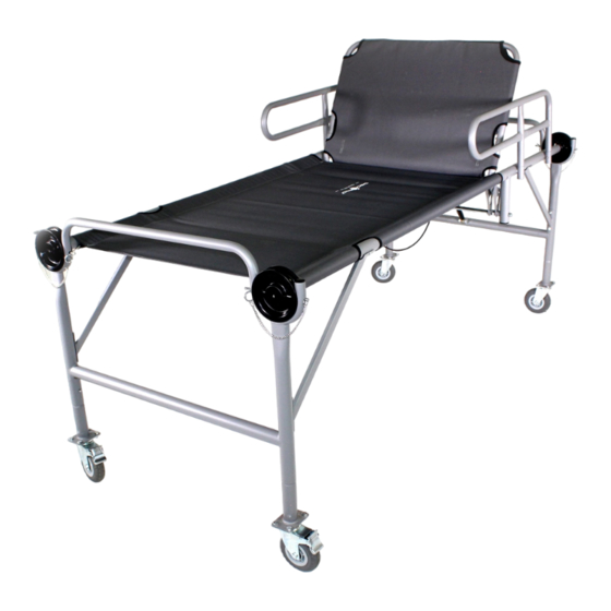
- Page 16 YOUR MOBILE CARE BED IS NOW COMPLETE. Ihr mobiles Pflegebett ist nun fertig aufgebaut.
-
Page 17: Packing Instructions
Packing Instructions... - Page 18 USAGE & CARE INSTRUCTIONS 1. This product is not designed or manufactured to be used outdoors. 2. Prolonged exposure to the elements will result in rapid deterioration of the product and void any warranty. 3. Ensure product is completely dry and clean before storing in climate controlled dry storage. 4.
-
Page 19: Warranty Conditions
WARRANTY CONDITIONS Our products are subject to strict quality controls. If a DISC-O-BED® product purchased from us does not work properly, we regret this very much and ask you to contact us at the contact address below at www.discobed.de. In addition to the statutory warranty, we grant you a guarantee on all DISC-O-BED products purchased from us, in accordance with the following provisions: YOUR LEGAL RIGHTS ARE NOT RESTRICTED BY THIS.
Need help?
Do you have a question about the 19890 and is the answer not in the manual?
Questions and answers