Table of Contents
Advertisement
Available languages
Available languages
Quick Links
CEBORA S.p.A.
MANUALE DI ISTRUZIONI PER KIT ANALIZZATORE ROBOT
I
CEBORA Art. 125.00.
INSTRUCTIONS MANUAL FOR CEBORA ROBOT ANALYZER
GB
KIT Art. 125.00.
MANUAL DE ISTRUCCIONES PARA KIT ANALIZADOR
E
ROBOT CEBORA Art. 125.00.
Finestra di LOG (fig. 6).
LOG Window (fig. 6).
Ventana del LOG (fig.6).
Collegamenti (fig. 7).
Connections (fig. 7).
Connexiones (fig.7).
Pagina Principale (fig. 8).
Main Page (fig. 8).
Página Principal (fig.8).
3.300.125-C
1
pag. 2
pag. 11
pag. 20
page 29
page 30
page 31
04/03/2016
Advertisement
Table of Contents

Subscribe to Our Youtube Channel
Summary of Contents for Cebora 125.00
- Page 1 CEBORA S.p.A. MANUALE DI ISTRUZIONI PER KIT ANALIZZATORE ROBOT pag. 2 CEBORA Art. 125.00. INSTRUCTIONS MANUAL FOR CEBORA ROBOT ANALYZER pag. 11 KIT Art. 125.00. MANUAL DE ISTRUCCIONES PARA KIT ANALIZADOR pag. 20 ROBOT CEBORA Art. 125.00. Finestra di LOG (fig. 6).
- Page 2 CEBORA S.p.A. IMPORTANTE: PRIMA DELLA MESSA IN OPERA • I campi magnetici derivanti da correnti elevate DELL'APPARECCHIO LEGGERE IL CONTENUTO possono incidere sul funzionamento di pacemaker. DI QUESTO MANUALE E CONSERVARLO, PER I portatori di apparecchiature elettroniche vitali TUTTA LA VITA OPERATIVA, IN UN LUOGO...
-
Page 3: Descrizione Generale
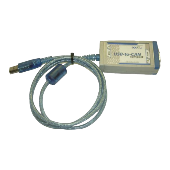
CEBORA S.p.A COMPOSIZIONE KIT. Il Kit Cebora Robot Analyzer è composto dagli elementi visibili in fig. 1. I cavi 2a e 2b sono uno in alternativa all’altro in funzione dell’impianto. fig. 1 Part. Descrizione Codice Quantità Modulo di interfaccia USB-to-CAN. -
Page 4: Pagina Principale
VCI2 con il nuovo VCI3, seguendo le Selezionare il Processo di lavorazione su cui è istruzioni contenute nel manuale "VCI - Virtual installato il Robot/Pantografo. CAN Interface, VCI-V3 Installation Manual, Click su OK per eseguire il programma “Cebora Software Version 3.2" (per informazioni Robot Analyzer”. -
Page 5: Descrizione Funzioni
CEBORA S.p.A Segnalazione funzioni. Operating Mode (MIG-TIG). Nella pagina principale sono presenti diversi Questa area indica la Operating Mode del indicatori a led: Generatore selezionata. In funzione di questa la - Luce Verde indica funzione attiva; Pagina Principale cambia. - Luce Rossa indica funzione non attiva. - Page 6 CEBORA S.p.A. Per rendere il Generatore pronto per la NOTA: Un errore può essere correttamente saldatura/taglio occorre disattivare il segnale acquisito solo se il segnale “Source Error “Quick Stop” (equivale ad attivare “Robot Reset” rimane inizializzato per almeno Ready”) ed attivare il segnale “Source Error 10 ms.
- Page 7 CEBORA S.p.A I segnali “Current Flow”, “Main Current” e 11.3 Inductance (MIG). “Process Active” sono inizializzati nello stesso Indica la “Correzione della Induttanza” espressa modo delle reali operazioni di saldatura. valore assoluto. Durante “Welding Simulation” sul Pannello di Il campo consentito è indicato nella linea.
- Page 8 CEBORA S.p.A. 11.8 Wire Low Speed Set Point (TIG). Dall’inizio del gas pre-flow fino alla fine del gas Indica il “Set Point della Velocità bassa del Filo post-flow, il Generatore inizializza il segnale Freddo” espresso in m/min. “Process Active” (fig. 5).
- Page 9 CEBORA S.p.A Il Controllo Robot arresta immediatamente il completamente srotolato, l’induttività del filo Robot e interrompe il processo di saldatura cambia ed il sistema cessa di rilevare il filo. tramite il segnale “Quick Stop”. Questa proprietà è utilizzata da un apposito circuito elettronico che genera l’allarme “fine del...
- Page 10 CEBORA S.p.A. 13.3 Motor Speed (MIG-TIG). 14 FINESTRA DI LOG. Indica il “Valore Reale della Velocità del La finestra di Log (fig 6) contiene informazioni Motore” espresso in m/min. referite alle variazioni dei parametric modificati, Il campo consentito è indicato nella linea.
-
Page 11: Safety Precautions
CEBORA S.p.A IMPORTANT: BEFORE STARTING • The magnetic fields created by high currents may EQUIPMENT, READ THE CONTENTS OF THIS affect the operation of pacemakers. Wearers of vital MANUAL, WHICH MUST BE STORED IN A PLACE electronic equipment (pacemakers) shall consult their... -
Page 12: Kit Composition
CEBORA S.p.A. KIT COMPOSITION. The Cebora Robot Analyzer Kit is made up of the elements visible in fig. 1. Cables 2a and 2b are alternative one each other, according to the plant characteristic. fig. 1 Part Description Code Quantity USB-to-CAN interface module. - Page 13 Select the working Process according with the follows the instructions of the “VCI - Virtual Robot-Pantograph installation. CAN Interface, VCI-V3 Installation Manual, Click on OK in order to execute the “Cebora Software Version 3,2” (for information contact Robot Analyzer” program. the Cebora Technical Service).
-
Page 14: Function Description
CEBORA S.p.A. Function signaling. Operating Mode (MIG-TIG). In the main page are several led indicators: This area shows the Power Source Operating - Green light indicates function active; Mode selected. Depending of the Operating - Red light indicates function not active. - Page 15 CEBORA S.p.A Making the Power Source ready for welding NOTE: An error can only be acknowledged deactivate the “Quick Stop” (equivalent to properly if the “Source Error Reset” initializes “Robot Ready”) and set the “Source signal remains initialised at least 10 ms.
- Page 16 CEBORA S.p.A. 10.10 AC / DC (TIG). 11.4 Burn-back Time Correction (MIG). Green light indicates AC welding current. Indicates the “Burn-back Time Correction” Red light indicates DC welding current. expressed in msec. The allowed range is shown on the line.
- Page 17 CEBORA S.p.A 12 DIGITAL SIGNALS FROM POWER The following are defined in the Power Source SOURCE TO ROBOT-PANTOGRAPH set-up menu (see Control Panel Instruction CONTROL. Manual): Digital output signals information is updated - HSA (Hot Start): starting current phase, with...
- Page 18 CEBORA S.p.A. “Power Source Ready” signal goes high and a 12.10 Pilot Arc (PLASMA). new welding operation can be started. Green light indicates function active. In case of impossibility in physically cutting the The “Pilot Arc” function remains active as long wire (inaccessible or too dangerous position), as the Pilot Arc is on.
- Page 19 CEBORA S.p.A 13.5 Current (PLASMA). 14 LOG WINDOW DESCRIPTION. Indicates the Cutting Current expressed in Log Window (fig 6) contents information absolute value. referred to modified parameters variations, with The allowed range is shown on the line. the following indication for each parameter: The corresponding Robot Interface Analogue - Parameter new value;...
- Page 20 CEBORA S.p.A. • Los campos magnéticos derivantes de corrientes IMPORTANTE: ANTES DE LA PUESTA EN elevadas pueden incidir en el funcionamiento de los FUNCIONAMIENTO DEL APARATO, LEER EL pacemaker. Los portadores de aparados electrónicos CONTENIDO ESTE MANUAL vitales (pacemaker) deben consultar el médico antes de...
-
Page 21: Descripción General
CEBORA S.p.A COMPOSICIÓN KIT. El Kit Cebora Robot Analyzer está compuesto de los elementos visibles en la fig. 1. Los cables 2a y 2b son uno en alternativa al otro según el sistema. fig. 1 Part Descripción Código Cant Módulo de interfaz USB-to-CAN. -
Page 22: Página Principal
Seleccionar el Proceso de trabajo correspondiente seguido las instrucciones contenidas en el al Robot-Pantografo instalado. manual "VCI - Virtual CAN Interface, VCI-V3 Clic en OK para ejecutar el programa “Cebora Installation Manual, Software Version 3.2" (para Robot Analizer”. informaciónes contactar el Servicio Técnico Aparece la Pàgina Principal, diferente segùn del... - Page 23 CEBORA S.p.A Operating Mode (MIG-TIG). Señalización funciones. Esta área indica la Operating Mode del Generador En la página principal están presentes distintos seleccionada. En función de ésta, la Página indicadores a led: Principal cambia. - Luz Verde indica función activa;...
- Page 24 CEBORA S.p.A. Para poner el Generador en listo para la NOTA:Un error puede adquirido soldadura/corte, desactivar la señal “Quick correctamente solo si la señal “Source Stop” (equivale a inicializar “Robot ready”) y Error Reset” permanece inicializada al activar la señal “Source Error Reset”.
- Page 25 CEBORA S.p.A Las señales “Current Flow”, “Main Current” y 11.3 Inductance (MIG). “Process Active” son inicializadas en la misma Indica la “Corrección de la Inductancia” expresa forma que las reales operaciones de soldadura. en valor absoluto. Durante “Welding Simulation” en el Panel de El campo concurrido se indica en la línea.
- Page 26 CEBORA S.p.A. 11.8 Wire Low Speed Set Point (TIG). Desde el inicio del gas pre-flow hasta el final del Indica el “Set Point de la Velocidad baja del gas post-flow, el Generador inicializa la señal Hilo Frjo” expreso en m/min.
- Page 27 CEBORA S.p.A El Control Robot para inmediatamente el Robot Antes de que la capa final sea completamente y interrumpe el proceso de soldadura mediante desenrollada, la inductividad del hilo cambia y el la señal “Quick Stop”. sistema deja de detectar el hilo. Esta propiedad es utilizada por un circuito electrónico apropiado que...
- Page 28 CEBORA S.p.A. 13.3 Motor Speed (MIG-TIG). 14 VENTANA DEL LOG. Indica el “Valor Real de la Velocidad del La ventana de Log (fig 6) contiene informaciónes Motor” expreso en m/min.. referite a las variaciónes de los paramétros El campo concurrido se indica en la línea.
- Page 29 CEBORA S.p.A. Finestra di LOG (par. 14). LOG window (par. 14). Ventana del LOG (par. 14). fig. 6 3.300.125-C 04/03/2016...
- Page 30 6 Welding wire spool holder. 27 USB-to-CAN module, included 7 Torch. “Cebora Robot Analyzer” Kit. 27A e 27B 8 Wire Feeder unit. connections are alternative between them. 1 Cable Generador – Panel de Control. 10 Funda del hilo de soldadura.
- Page 31 CEBORA S.p.A. fig. 7b PLASMA system. fig. 8a MIG System Main Page. 3.300.125-C 04/03/2016...
- Page 32 CEBORA S.p.A. fig. 8b TIG System Main Page. fig. 8c PLASMA System Main Page. 3.300.125-C 04/03/2016...
Need help?
Do you have a question about the 125.00 and is the answer not in the manual?
Questions and answers