Table of Contents
Advertisement
Quick Links
NANOMETER
THREE-PHASE STATIC
MULTI-FUNCTIONAL METER (MFM)
• LOW VOLTAGE ELECTRICAL DISTRIBUTION
• EXTERNAL CURRENT TRANSFORMER (CT)
• MULTIFUNCTION DISPLAY
• HARMONIC ANALYSIS
• DIGITAL INPUT / OUTPUT
• EDS COMMUNICATION
• STANDARD 4-WAY DIN-RAIL MOUNT
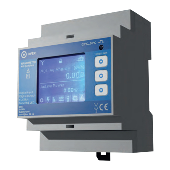
The NanOMeter is a static meter of active and reactive energy, designed for a standard 4-way DIN-rail mount,
for three-phase systems with or without connecting to the neutral line. The large LCD display enables clear
visualization of the total active and reactive energy, active and reactive power (total and per phase), of the
phase voltage, of the phase current and of the power factor. Moreover, the meter provides the option to
display harmonic analysis of the individual phases. The presence of the buttons allows you to perform basic
programming operations. The device is also equipped with 2 programmable interfaces (1 digital IN and 1
digital OUT).
Version 1.2 - Subject to change without notice
Advertisement
Table of Contents

Summary of Contents for OVER NANOMETER NE2
- Page 1 NANOMETER THREE-PHASE STATIC MULTI-FUNCTIONAL METER (MFM) • LOW VOLTAGE ELECTRICAL DISTRIBUTION • EXTERNAL CURRENT TRANSFORMER (CT) • MULTIFUNCTION DISPLAY • HARMONIC ANALYSIS • DIGITAL INPUT / OUTPUT • EDS COMMUNICATION • STANDARD 4-WAY DIN-RAIL MOUNT The NanOMeter is a static meter of active and reactive energy, designed for a standard 4-way DIN-rail mount, for three-phase systems with or without connecting to the neutral line.
- Page 2 DATA SHEET MODEL NanOMeter PRODUCT CODE RoHS, CE CERTIFICATIONS UAE RoHS, ECAS MAXIMUM MEASUREMENT ERROR ±0,5% 12÷15Vdc POWER SUPPLY or auxiliary power supply 230Vac CURRENT DRAW max 30mA at 13,9V SIZE 90x70x59mm - 4 DIN modules WEIGHT 120g COMMUNICATION BUS NOMINAL VOLTAGE 3x230Vac NETWORK FREQUENCY...
-
Page 3: Maximum Bus Length
EDS BUS SPECIFICATIONS MAXIMUM BUS 1200m linear BUS LENGTH <10m <30m <100m >100m LENGTH over the whole system Star, series or RECOMMENDED 0,50 0,75 BUS TOPOLOGY promiscuous MINIMUM SECTION mm² mm² mm² mm² 1,5mm² is recommended for implants, a value which however depends on the location of the modules... -
Page 4: Front Panel
COMPONENTS Two rows of input/output terminals are located on the top and bottom of the devi- CURRENT VOLTAGE ce. On the top of the device is the group of current inputs and the group of voltage INPUT INPUT inputs. On the bottom of the device, there is the group for the digital outputs, one L1 N L3 L2 for the BUS communication and another for the auxiliary power supply. - Page 5 VOLTAGE AND CURRENT METER CONNECTIONS VOLTMETRIC CONNECTIONS AMPEROMETRIC CONNECTIONS Use cables with a max section of 2,5 mm if flexible, 4 mm if rigid and Use CTs with adequate primary and secondary 5A. Connect the connect them to the marked terminals with voltage input according to the amperometric signals coming from the CTs to the marked terminals by L1, diagrams in the figure.
- Page 6 PROGRAMMING Once the device is connected, enter ‘programming mode’ using the appropriate switch. In the programming mode it is possible to affirm the direction BUTTON of connection of the CTs to the respective terminals are correct, check the sequence of phases, specify the size of the CTs supplied to the device, change the address of the device on the BUS, test if connection of the digital input and that of the digital output are correct.
-
Page 7: Operation
DIGITAL OUT TEST DIGITAL OUT TEST ADDRESS DIGITAL OUT TEST DIGITAL OUT TEST DIGITAL OUT TEST DIGITAL OUT TEST Set Network Set Channel ERROR CLICK CLICK CLICK CLICK PROGRAMMING BUTTON BUTTON BUTTON BUTTON COMPLETED Digital output and input test DIGITAL OUT TEST DIGITAL OUT TEST In the third tab you can check the digital output and input ADDRESS... - Page 8 2.0.1 Tot. Active Energy 0.0V 0.000A FW Version kVar EDS Bus 0.99 6.34 A 0.0V 0.000A 0.0000000 150/5 0.0V 0.000A Programming Restart 0.0V 0.000A 0.97 6.93 A TA Factor Active Power 0.0V 0.000A 0.00 0.0V 0.000A NANO MID : 001 NANO MID : 001 NANO MID : 001 NANO MID : 0...
- Page 9 Once the programming procedure is complete, check the connection of the NanOMeter and the related CTs. A properly functioning system should show all cosφ> 0.95 and an equitable load distribution over the three phases. Old electrical systems may have accumulated changes over time which can lead to a recoding of cosφ>...
-
Page 10: Warranty
RETURN AND REPAIR PROCEDURE All returned products must be returned in the same condition in which they were supplied at the Buyer’s expense, to the headquarters of Over S.p.A. in Viale Piemonte 37 - 20093 Cologno Monzese (MI) and packed by the Buyer in order to avoid damages for which the Buyer himself would be responsible.
Need help?
Do you have a question about the NANOMETER NE2 and is the answer not in the manual?
Questions and answers