Table of Contents
Advertisement
Quick Links
Advertisement
Table of Contents

Summary of Contents for Mesa MQC Series
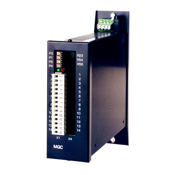
- Page 1 PWM SERVO CONTROLLERS SERIES MQC Operating Manual Issue September...
- Page 2 MESA Automation GmbH RECEIVING AND HANDLING Upon delivery of the equipment, inspect the shipping containers and contents for indications of damages in curried in transit. If any of the items specified in the bill of lading are damaged, or the quantity is incorrect, do not accept them until the freight or express agent makes an appropriate notation on your freight bill or express receipt.
-
Page 3: Table Of Contents
TECHNICAL SPECIFICATIONS FOR MQC ....................2 ............................3 ASIS MODELS ............................3 RDER EXAMPLE GENERAL CONDITIONS ...........................3 BLOCK DIAGRAM............................4 OPT E L ......................5 UBPRINT IMIT SWITCH MSM-OPT ..........................5 UBPRINT POWER SUPPLY ............................5 ± 15 V........................5 LECTRONIC SUPPLY ...........................5 OWER TRANSFORMER SETTING UP THE AMPLIFIER ........................5 : P3 ........................5 ACHO ADJUSTMENT : P1............................5... -
Page 4: Technical Specifications For Mqc
MESA Automation GmbH 1 Technical specifications for MQC Power stage Input voltage Chapter 1.1 Basis models Over voltage protection 85 VDC (U =60 V) 160 VDC (U =120 V), 190 VDC (U =150 V) Chopper frequency 8 kHz (to GND) Form factor at nominal ratings 1.01 (Rated current) -
Page 5: Basis Models
MESA Automation GmbH 1.1 Basis models TYPE NRMS (V DC) (V AC) (V AC) (V AC) MQC 0506 24 -48 V DC 16 V DC 65 V DC MQC 0510 24 -48 V DC 16 V DC 65 V DC... -
Page 6: Block Diagram
MESA Automation GmbH 3 Block diagram MQC 05 V 3 EM... -
Page 7: Subprint Opt E Limit Switch
MESA Automation GmbH 3.1 Subprint OPT E Limit switch By connection of GND (OPT E -) or 24 V signal (OPT E +) to the terminals for negative and positive direction the limit switch can be deactivated. If the limit switch is active, the motor will stop in these direction. The limit switch logic level (OPT E += positive, OPT E (-)= negative logic) is set by factory. -
Page 8: Adjustment Of The Speed Controller Gain
MESA Automation GmbH 5.3 Adjustment of the speed controller gain Amplifiers are equipped with a standard optimisation and can be adapted by P2. Is this adjustment not possible, PI on the Personality card must be checked. P-Gain: P2 Standard range:... -
Page 9: Armature Current Measurement
MESA Automation GmbH 5.4 Armature Current Measurement Armature current is measured by means of a shunt placed in series with the armature circuit. The voltage produced can be measured at the „I Monitor“ test point. 10 Volts output corresponds to the maximum current of the amplifier. -
Page 10: Variable Components
MESA Automation GmbH 5.7 Variable components 10 k Ω Set value adjustment: R111 Standard: Tacho adjustment: Standard: 1,8 kΩ IxR compensation: Standard: not used 5.8 Speed controller components, Block diagram lntegral part C2 Standard: C2 = 0,1 µF Proportional part P2 / R 21 Standard: R21 = 82 kΩ... -
Page 11: Current Control
MESA Automation GmbH 5.9 Current control The controller is optimised by factory, do not change ! 6 Protection and fault signalling The green LED indicates the proper function of the unit. In case of a fault, a signal is given by the front red LED (H1), power stage will be disable and the „ready/drive healthy"... -
Page 12: Faultfinding And Remedy
MESA Automation GmbH 8 Faultfinding and remedy Fault Cause Remedy The motor will not start supply voltage missing check all fuses are good and supply voltage are present there is no current drive not enable Terminal X1/Pin5 should be connected to 0VDC... -
Page 13: Solder Jumper
MESA Automation GmbH 9.2 Solder jumper Solder jumper Function (closed) Remark BR 1 Drive output to Tacho input BEMF control BR 2 Drive output to Tacho input BEMF control BR 3 Tacho input to GND disturbance reduction BR 4 P-connector R= 1,8 KΩ... -
Page 14: Technical Dates - Drive Braking Module
MESA Automation GmbH 9.5 Technical Dates - Drive Braking module Type (V DC) (V DC) BR ON BR OFF cont. MQC 0506 MQC 0510 MQC 0606 MQC 0610 MQC 1206 1800 MQC 1208 1800 MQC 1210 1800 MQC 1510 2200... -
Page 15: Drawings
MESA Automation GmbH 10 Drawings 10.1 Amplifier input 10.2 DC-Power supply Attention ! Do not ground the secondary winding ! MQC 05 XX L1’;L2’;L2’ DC Input ! MQC 05 V 3 EM... -
Page 16: Components Location
MESA Automation GmbH 10.3 Components location MQC 05 V 3 EM... -
Page 17: Mechanical Style
MESA Automation GmbH 10.4 Mechanical style MQC 05 V 3 EM... - Page 18 MESA Automation GmbH The manual is subject to modifications or misprint. Please call our service for further technical questions. MQC 05 V 3 EM...
- Page 19 MESA Automation GmbH MQC 05 V 3 EM...
- Page 20 MESA Automation GmbH Mesa Automation GmbH Member of Infranor group 12045 Berlin Maybachufer 48-51 Tel: +49 - (0)30 - 6139080 Telefax : +49 - (0)30 - 6231766 http://www.mesa-berlin.de Email service @mesa-berlin.de MQC 05 V 3 EM...
Need help?
Do you have a question about the MQC Series and is the answer not in the manual?
Questions and answers