Table of Contents
Advertisement
Quick Links
User Manual
PolyGard
®
2 DGC6
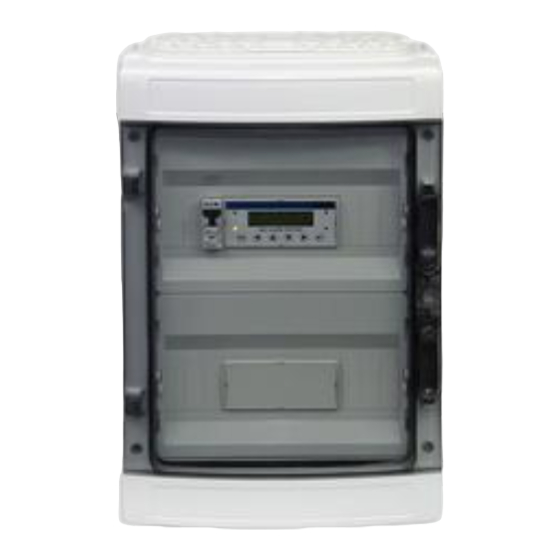
Digital Gas-Controller-Series GC-06 Modbus
Modbus Supplement
December 09, 2022 – Revision
Version:
Language:
INTEC Controls | 12700 Stowe Drive, Suite 100, Poway, CA 92064 | Ph: (858) 578.7887 & (888) GO.INTEC | inteccontrols.com
2022-04
English
Release date:
Name of file:
2022-04-05
GA_GC06_Modbus_supple-
ment_E
Advertisement
Table of Contents

Summary of Contents for MSR ELECTRONIC Intec Controls PolyGard 2 GC-06 Series
- Page 1 User Manual PolyGard ® 2 DGC6 Digital Gas-Controller-Series GC-06 Modbus Modbus Supplement December 09, 2022 – Revision Version: 2022-04 Release date: 2022-04-05 Language: English Name of file: GA_GC06_Modbus_supple- ment_E INTEC Controls | 12700 Stowe Drive, Suite 100, Poway, CA 92064 | Ph: (858) 578.7887 & (888) GO.INTEC | inteccontrols.com...
- Page 2 This page intentionally left blank...
-
Page 3: Table Of Contents
DGC6 Modbus Supplement – UserManual Specifications subject to change without notice. | GA_GC06_Modbus_supplement_E, 2022-04-05 | USA 221209 | Page 3 of 12 Table of Contents General ............................4 1.1 Safety ................................ 4 1.2 Responsibility Installer and Operator ....................4 1.3 Maintenance ............................4 1.4 Limited Warranty ........................... -
Page 4: General
DGC6 Modbus Supplement – UserManual Specifications subject to change without notice. | GA_GC06_Modbus_supplement_E, 2022-04-05 | USA 221209 | Page 4 of 12 1 General 1.1 Safety The operating instructions must be carefully read and followed by all persons who install, use, main- tain and check the product. -
Page 5: Limited Warranty
DGC6 Modbus Supplement – UserManual Specifications subject to change without notice. | GA_GC06_Modbus_supplement_E, 2022-04-05 | USA 221209 | Page 5 of 12 1.4 Limited Warranty INTEC Controls | MSR-Electronic GmbH does not assume any liability in case of improper or incorrect use of the de-vice. -
Page 6: Serial Modbus Interface At The X-Bus
DGC6 Modbus Supplement – UserManual Specifications subject to change without notice. | GA_GC06_Modbus_supplement_E, 2022-04-05 | USA 221209 | Page 6 of 12 2 Serial Modbus Interface at the X-BUS This functionality is available from display version 1.00.06 on. The standard protocol for an additional serial port of the gas controller X bus is ModBus RTU. -
Page 7: Average Value Of Digital Sensors - Sensor Addr. 1-96, Modbus Register Addr. 3001-3096
DGC6 Modbus Supplement – UserManual Specifications subject to change without notice. | GA_GC06_Modbus_supplement_E, 2022-04-05 | USA 221209 | Page 7 of 12 Representation of measured values: The measured values are shown in the Integer format with a factor of 1, 10, 100 or 1000. The factor depends on the respective measuring range and is used as follows: Measuring range Factor... -
Page 8: Display Of The Alarms And The Respective Latching Bits Of Digital Sensors
DGC6 Modbus Supplement – UserManual Specifications subject to change without notice. | GA_GC06_Modbus_supplement_E, 2022-04-05 | USA 221209 | Page 8 of 12 3.7 Display of the alarms and the respective latching bits of digital sensors Display of the local alarms generated by the DGC-06 as well as of the respective latching bits of digital sensors –... -
Page 9: Relay Status Of The Signal Relays - Signal Relay Addr. 1-96, Modbus Register Addr. 7001-7096
DGC6 Modbus Supplement – UserManual Specifications subject to change without notice. | GA_GC06_Modbus_supplement_E, 2022-04-05 | USA 221209 | Page 9 of 12 3.9 Relay status of the signal relays – signal relay addr. 1–96, Modbus register addr. 7001–7096 3.10 Relay status of the alarm relays – alarm relay addr. 1–32, Modbus register addr. 8001–8032 Figure 7: Relay status of the alarm relays –... - Page 10 DGC6 Modbus Supplement – UserManual Specifications subject to change without notice. | GA_GC06_Modbus_supplement_E, 2022-04-05 | USA 221209 | Page 10 of 12 a) Register address 9000d: Local error of the connected GC device – errors apply to the devices not to the readings of these devices. Here 0x8110: 0x0100 =>...
-
Page 11: Dgc-06 Watch Outputs (Wi), Modbus Register Addresses 50-57
DGC6 Modbus Supplement – UserManual Specifications subject to change without notice. | GA_GC06_Modbus_supplement_E, 2022-04-05 | USA 221209 | Page 11 of 12 3.12 DGC-06 Watch Outputs (WI), Modbus register addresses 50–57 In register 50, all watch outputs are shown as a byte as used for evaluation in the DGC-06 system. -
Page 12: Modbus-Function 05 (Write Single Coil)
DGC6 Modbus Supplement – UserManual Specifications subject to change without notice. | GA_GC06_Modbus_supplement_E, 2022-04-05 | USA 221209 | Page 12 of 12 4 Modbus-Function 05 (Write Single Coil) Write Single Coil (writing of single states ON/OFF) is used to acknowledge the latching mode or the horns as well as to set clock outputs individually.


Need help?
Do you have a question about the Intec Controls PolyGard 2 GC-06 Series and is the answer not in the manual?
Questions and answers