
Related Manuals for Payter APO01 PAY V1-X Series

Summary of Contents for Payter APO01 PAY V1-X Series
- Page 1 User Manual Payter B.V. Rozenlaan 115 3051 LP Rotterdam The Netherlands V1.3 - 202301 Page 1 of 43...
- Page 2 Payter reserves the right to modify specifications stated in this manual. Liability Payter B.V. accepts no liability for claims arising from improper use other than that stated in this manual of from not obeying (safety) instructions and precautions in this manual. Although considerable care has been taken to ensure a correct and suitably comprehensive description of the product, this manual may nonetheless contain errors and inaccuracies.
- Page 3 − Response code and error list − Payter session protocol document − Payter Cloud Payments Service document Professionals responsible for integration of the Apollo terminal into the host machine, may also refer to: − Mechanical integration manual You can find request these additional documents at through your account representative or via support@payter.nl...
- Page 4 Multidrop Bus (i.e. a communications bus standard for vending machines). Milliseconds NAMA National Automatic Merchandising Association Near Field Communication Payment Service Provider Quick Response Payter Vending Protocol Remote Terminal Protocol Software Development Kit Subscriber Identification Module Universal Serial Bus Vending Machine Controller Payment Card Industry Security Standards Council...
-
Page 5: Table Of Contents
Modes of operation ..................16 Machine Interface ....................... 16 MDB mode .......................... 16 Internet connection ..................17 Firewall network settings for the Payter Payment Terminal..........17 User Interface ....................18 Customisation ........................18 Example Payment flow ......................18 Configuration ....................19 Access .......................... - Page 6 User Manual Installation and User Guidance ................... 30 11.5.1 Initial Inspection ........................30 11.5.2 Installation ........................... 30 Environmental Conditions ....................31 Communications and Security Protocols ................31 Configuration Settings ......................31 Operation and Maintenance ................31 Periodic Inspection ......................31 Self-Test ..........................
-
Page 7: Introduction
Failure to charge the batteries at notification by the MyPayter Terminal management System can result in tampering the terminal. A tampered terminal need to be returned to Payter for analysis, possible replacement of the batteries and key injection. V1.3 - 202301... -
Page 8: Safety
Security All Payter Point of Sale terminals are certified by the card schemes according to the latest standards and accredited through various acquirers to securely process transactions. The integrity of the payment terminals is crucial, because they process sensitive card data. -
Page 9: The Apollo Terminal
User Manual 3. The Apollo Terminal The Apollo and ApolloMax are PIN Entry Devices (PED) for payment processing in unattended environments. The terminals have the ability to provide contact, contactless and magstripe transactions. The terminals supports the following main features •... -
Page 10: Apollo Terminal
User Manual Apollo terminal Figure 2: Front of the Apollo terminal Item Description LEDs (4) Multi colour status LEDs Camera and Locator light Enabling QR-Code reading Proximity sensor WiFi & Bluetooth Module 3,5 Inch touch screen Speaker V1.3 - 202301 Page 10 of 43... -
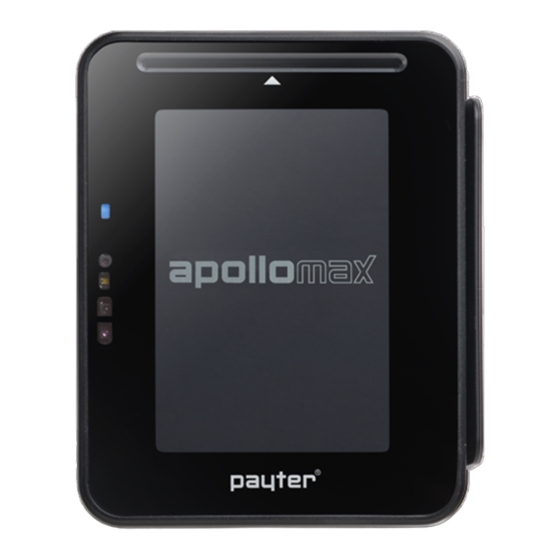
Page 11: Apollomax Terminal
User Manual ApolloMax terminal Figure 3: Front of the ApolloMax terminal Item Description LEDs (4) Multi colour status LEDs Camera and Locator light Enabling QR-Code reading Proximity sensor Chip Card Reader WiFi & Bluetooth Module Magnetic Stripe reader 3,5 Inch touch screen Speaker V1.3 - 202301 Page 11 of 43... -
Page 12: Connections
User Manual Connections Figure 4: Rear side of the Apollo terminal Item Description USB-C port Host and Slave Connector Micro Fit MDB connector Port to connect with the internet through the LAN. 4G/ GPS modem Modem with GPS functionality (optional) RJ 45 LAN Connector Port for USB-C cable to interface with the terminal from the host machine. -
Page 13: Power Connection
User Manual Power connection The terminals require an external power supply for operation, using two options through the Micro fit connector: Provided 220V power supply MDB or similar bus Please find below the specification for connecting the terminal: VDC = 12..24V P = 18W max. -
Page 14: Dimensions Antenna
An offset of 5 mm along the sides and rear of the terminal will provide enough distance. If you have any questions with regards to the mechanical integration, please contact the Payter support desk. Placing the antenna 1. -
Page 15: Interfaces, Connections And Terminal Configuration
Executive The Apollo series terminals can be combined with the VendBox to enable executive mode functionality. The VendBox is a Payter product and acts as a converter between the executive and the MDB interface. Potential Free... -
Page 16: Modes Of Operation
Table 5.1 – Available Host Machine interface modes. For detailed and in depth information about the various interfaces, please check the Payter website for documentation or ask your Payter account representative. MDB mode MDB stands for multidrop bus. -
Page 17: Internet Connection
This problem must be resolved before you continue. Firewall network settings for the Payter Payment Terminal When the terminal is connected through the LAN Cable or WiFi, it will require open ports in the Firewall. -
Page 18: User Interface
User Manual 7. User Interface Customisation The following parts of the user Interface can be customized to reflect your company brand: Small Logo in display Background colour Thank you message Idle screens prior to the start of transaction, i.e. with product placement Example Payment flow Idle screens... -
Page 19: Configuration
User Manual 8. Configuration The Apollo terminals are continuous connected to the Payter Terminal Management System (TMS). The configuration of the terminals, including Key loading can only be done through the MyPayter TMS portal. The MyPayter portal allows: • Efficient and timely deployment of keys, configuration updates and payment device firmware •... -
Page 20: Mechanical Integration
User Manual 9. Mechanical Integration Front mounting The Apollo series terminals can be directly mounted on the front panel of a machine. The mounting footprint of Figure 5 is applicable for both the Apollo and the ApolloMax terminal. Make sure that there is an opening in your machine large enough to accommodate the placement of the MDB/power cable and antenna cable or the LAN cable indicated by the orange rectangular in below figure. -
Page 21: Eva Mounting
User Manual EVA mounting The majority of the vending machines have a provision for installing payment terminals. The dimensions of the Apollo series terminals are based on the European Vending Association (EVA) standard. 9.2.1 Device opening Mounting an Apollo series terminal requires a device opening that complies with the EVA EPS – standard door model measurements (see Figure 6). -
Page 22: Eva Mounting Option 1: Studs In Machine
User Manual 9.2.2 EVA mounting option 1: studs in machine If the vending machine has pre-installed studs (see Figure 6): 1. Position the mounting frame at the rear of the opening. 2. Secure the terminal and frame with the four M4 nuts supplied with the terminal. For a clean and neat finish of the front, do not forget to place the cover plate at the front of the machine. -
Page 23: Eva Mounting Option 2: No Studs In Machine
User Manual 9.2.3 EVA mounting option 2: no studs in machine If the machine does not come with pre-installed studs: 1. Position the supplied mounting frame on the front of the vending machine. 2. Drill mounting holes with a diameter of 4 millimetres at the indicated well stud positions. 3. -
Page 24: Dimensions Apollo Terminal
User Manual Dimensions Apollo terminal Figure 11: Dimension Apollo terminal without frame Figure 12: Dimension Apollo terminal with frame V1.3 - 202301 Page 24 of 43... -
Page 25: Dimensions Apollomax Terminal
User Manual Dimensions ApolloMax terminal Figure 13: Dimensions ApolloMax terminal without frame Figure 14: Dimensioins ApolloMax terminal with frame V1.3 - 202301 Page 25 of 43... -
Page 26: Merchant Responsibilities Security
User Manual 10. Merchant Responsibilities Security All Payter Point of Sale terminals are certified by the card schemes according to the latest standards and accredited through various acquirers to securely process transactions. The integrity of the payment terminals is crucial, because they process sensitive card data. Regularly inspect your payment terminal to ensure it is secure. -
Page 27: Transactions And Reconciliation
Customer’s Merchant Account with the Transactions processed by the Payment Terminal and PSP Service. In the event that the Customer identifies a discrepancy they must notify Payter as soon as reasonably practical. Payter and the PSP will treat any such notification as a high priority problem. -
Page 28: Faulty, Lost, Stolen, Or Damaged/Tampered Terminals
Terminal integrity inspections on a weekly basis as well as before and after storage of the Terminals. In case of any doubts, do not use the terminal and contact Payter via the regular escalation channels. -
Page 29: Pci Security
User Manual 11. PCI Security This chapter describes how to operate the Apollo payment terminal in a secure manner. The terminal is approved to PCI-PTS V6.0, this document describes how to use the device in a manner compliant to the requirements set out in PCI-PTS V6.0. Using the terminal in a way that deviates from this document will invalidate the PCI PTS approval of the device. -
Page 30: Firmware
User Manual 11.3.2 Firmware This document applies to any firmware version as per below. Location of Identifiers The hardware and firmware identifiers are presented during the boot process. The hardware identifier is also printed on a label on the back of the device. The identification label shall not be torn off or altered in any way. -
Page 31: Environmental Conditions
The security protocols should be used in accordance with the Application Developer Guidance [1]. Configuration Settings The terminal enforces all settings necessary to meet the PCI requirements. Payter manages a remote key loading facility which ensures all security critical settings are deployed securely. -
Page 32: Passwords And Certificates
User Manual Passwords and Certificates All applications have to be signed by Payter following a review of the application, optionally an Acquirer can be issued its own application signing certificate but it is the acquirer’s responsibility to ensure a secure environment to generate the required RSA key pair and associated certificate signing request. -
Page 33: Signing
User Manual Signing The Apollo will only run applications that provide a signature created using a certificate that has been issued by the Payter Root certificate. Applications are signed using RSA 4096 for signature verification and SHA256 calculating data integrity hashes. - Page 34 User Manual Loaded : TR-31 1 per Crypto DUKPT 2009 IPEK DUKPT-IPEK-2009 2TDEA Stored : N/A Domain 2TDEA Loaded : TR-31 1 per Crypto DUKPT 2017 IPEK DUKPT-IPEK-2017 3TDEA Stored : N/A Domain Loaded : NA DUKPT 2009 Future 21 per Crypto DUKPT-FK-2009 2TDEA Stored : OPTEE...
-
Page 35: References
User Manual Loaded : TR-31 1 per Crypto CONLON CONLON 2TDEA Stored: OPTEE Domain Object References 1. Application Developer Guidance 2. Application Signing 3. ANS X9.24-1:2009, Retail Financial Services Symmetric Key Management Part 1: Using Symmetric Techniques 4. ANS X9.24 - 3: 2017, Retail Financial Services Symmetric Key Management Part 1: Unique Key Per Transaction 5. -
Page 36: Technical Specifications
User Manual 14. Technical specifications EMVCo. L1 v3.0 Certified ISO14443 Type A & B (T=CL) Depending on the card/token Contactless Interface Mifare Classic protocol Operating Distance up to 10 cm from Reader Desfire protocol ISO18092: Support NFC Protocol CE, FCC, RoHS, WEEE , REACH EMVCo, PCI-PTS 6.x, TQM Contact Card Interface EMV L1 v4.3 Certified... -
Page 37: Troubleshooting
User Manual 15. Troubleshooting HTTP Error codes 900 Informational (1××) 934 Conflict (409) 901 Continue (100) 935 Gone (410) 902 Switching Protocols (101) 936 Length Required (411) 903 Processing (102) 937 Precondition Failed (412) 904 Success (2××) 938 Payload Too Large (413) 905 OK (200) 939 Request-URI Too Long (414) 906 Created (201) -
Page 38: Creditcall/Nmi Error Codes
User Manual Creditcall/NMI Error codes V1.3 - 202301 Page 38 of 43... -
Page 39: Issuer Decline Codes
User Manual Issuer Decline Codes Response Description Declined - Call Issuer Declined – Limits reached, PIN required Declined - Pick Up Card Declined - Do Not Honor Declined - Partial Approval Declined - Invalid Transaction Declined - Card Amount Invalid Declined - Card Number Invalid Declined - No Such Issuer Declined - Re-Enter... -
Page 40: Declaration Of Conformity
User Manual 17. Declaration of Conformity Manufacturer Name: Payter B.V. Manufacturer Address: Rozenlaan 115 3051LP Rotterdam The Netherlands Hereby declares that the products, Product Name: Apollo, ApolloMax Product Description: Contactless Payment Terminal Product Model Number(s): APO01.XX.PAY V1-X, APM01.XX.PAY V1-X Product Model Options:... -
Page 41: Fcc
Caution Changes or modifications made to this equipment not expressly approved by Payter BV may void the FCC authorization to operate this equipment. -
Page 42: Family Letter
User Manual 19. Family Letter DECLARATION OF CONFORMITY (DoC) Manufacturer Name: Payter B.V. Manufacturer Address: Rozenlaan 115 3051LP Rotterdam The Netherlands Hereby declares that the following products constitute a family. They share the same hardware and software platform; including but not limited to all EMV L1, L2 and payment application modules. -
Page 43: Rohs-3 Certificate Of Compliance
Diisobutyl phthalate (DIBP): < 1000 ppm Based on the information provided by our suppliers, and to the best of our knowledge, Payter B.V. designates that Payter B.V. listed products are RoHS Compliant and conform to the European Union Restrictions of the use of Hazardous Substances.
Need help?
Do you have a question about the APO01 PAY V1-X Series and is the answer not in the manual?
Questions and answers