Advertisement
Quick Links
Instruction and
Installation Manual
Manning VL-F7-LPA Gas Sensor
18394 VLF7LPA 02/2005 REVF Copyright © 2005 Manning Systems, Inc. All Rights Reserved.
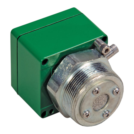
VL-F7-N4-LPA-MK
Vent Line Sensor
for Ammonia and
Other Refrigerants
Linear 4/20 mA Output
MOUNT ENCLOSURE THIS END UP.
DO NOT BLOCK PERFORATED VENT HOLES.
PRE-AMP
®
405 Barclay Boulevard
Lincolnshire, Illinois 60069
Tel: +1 847 955 8200
Toll free: +1 800 538 0363
Fax: +1 847 955 8208
detectgas@honeywell.com
18394 VLF7LPA 07/2016 REV H
1
Advertisement

Related Manuals for Manning VL-F7-N4-LPA-MK

Summary of Contents for Manning VL-F7-N4-LPA-MK
- Page 1 Lincolnshire, Illinois 60069 Tel: +1 847 955 8200 Toll free: +1 800 538 0363 Fax: +1 847 955 8208 detectgas@honeywell.com 18394 VLF7LPA 07/2016 REV H Manning VL-F7-LPA Gas Sensor 18394 VLF7LPA 02/2005 REVF Copyright © 2005 Manning Systems, Inc. All Rights Reserved.
- Page 2 Introduction This manual has been prepared to help in the use and installation of the Manning Systems VL-F7-LPA Vent Line Sensor. This manual will convey the operating details of the sensor, ensure proper installation, and demonstrate start-up and routine maintenance procedures.
- Page 3 Proper location in mounting the vent line sensor is the key to long and trouble-free life. Carefully review the mounting instruction portion of this manual. 6 3/4" PRE-AMP ® Manning VL-F7-LPA Gas Sensor 18394 VLF7LPA 02/2005 REVF Copyright © 2005 Manning Systems, Inc. All Rights Reserved.
- Page 4 (Belden #8770), maximum run length 1,500 feet • Sensor to pre-amp – #16 AWG, 4 conductors, non-shielded for runs up to 25 feet Specifications subject to change without notice. Manning VL-F7-LPA Gas Sensor 18394 VLF7LPA 02/2005 REVF Copyright © 2005 Manning Systems, Inc. All Rights Reserved.
- Page 5 Always assume a relief valve could release at any moment. Always treat vent line systems with extreme caution (see Figure 2). Manning VL-F7-LPA Gas Sensor 18394 VLF7LPA 02/2005 REVF Copyright © 2005 Manning Systems, Inc. All Rights Reserved.
- Page 6 Flow meter Regulator Compressed air supply Check valve Water level Needle valve Filter Relief header Tie in at lowest point Water purge tank Manning VL-F7-LPA Gas Sensor 18394 VLF7LPA 02/2005 REVF Copyright © 2005 Manning Systems, Inc. All Rights Reserved.
- Page 7 12 TO 24 VDC 4 - 20 mA 25' maximum— 16 AWG, 3-conductor #18 AWG shielded ORANGE 4 conductors, non-shielded (Belden #8770 or equivalent) ORANGE Manning VL-F7-LPA Gas Sensor 18394 VLF7LPA 02/2005 REVF Copyright © 2005 Manning Systems, Inc. All Rights Reserved.
- Page 8 Due to environmental differences and background gases, the installed clean air signal may be different than it was during factory calibration. This difference can be zeroed out. Manning VL-F7-LPA Gas Sensor 18394 VLF7LPA 02/2005 REVF Copyright © 2005 Manning Systems, Inc. All Rights Reserved.
- Page 9 Always be prepared and wear appropriate 12 TO 24 VDC 4 - 20 mA Black protective gear such as a face shield and gloves. Manning VL-F7-LPA Gas Sensor 18394 VLF7LPA 02/2005 REVF Copyright © 2005 Manning Systems, Inc. All Rights Reserved.
- Page 10 OCCURRED. elements, cartridges, or lter elements. Manning VL-F7-LPA Gas Sensor Manning VL-F7-LPA Gas Sensore 18394 VLF7LPA 07/2016 REVH Manning VL-F7-LPA Gas Sensor 18394 VLF7LPA 07/2016 REVH 18394 VLF7LPA 02/2005 REVF Copyright © 2005 Manning Systems, Inc. All Rights Reserved.
Need help?
Do you have a question about the VL-F7-N4-LPA-MK and is the answer not in the manual?
Questions and answers