
Subscribe to Our Youtube Channel
Related Manuals for Competition Electronics DH16A-10DT-B

Summary of Contents for Competition Electronics DH16A-10DT-B
- Page 1 Instruction Manual DH16A-10DT-B DH16A-30DT-B DH16A-50DT-B DH16A-12DT-B DH16A-52DT-B DH16A-62DT-B DH16A-83DT-B 2022-V01...
- Page 2 ≤110mA Applicable card mode: EM ID card(Default) T5557/T5567 card(Setting required) Effective distance: 2-3cm DH16A-10DT-B Capacity: ZONE 1: up to 1000 passwords & card holders ZONE 2: up to 10 passwords OR card holders 1. With internal EM reader.
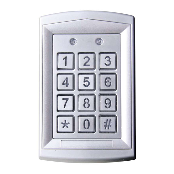
- Page 3 Description Mode indicator Door indicator Antenna Matrix keypads Case screw Working conditions: temperature: -20 C ~ +50 C RH:≤95% Current and voltage requirements: DC input: +12V - +24V AC input: ~ 12V - 24V standby current: ≤80mA working current: ≤110mA Applicable card mode: EM ID card(Default) T5557/T5567 card(Setting required)
- Page 4 Description Mode indicator Matrix keypads Antenna Case screw Working conditions: temperature: -20 C ~ +50 C RH: ≤95% Current and voltage requirements: DC input: +12V - +24V AC input: ~ 12V - 24V standby current: ≤80mA working current: ≤110mA Applicable card mode: EM ID card(Default) T5557/T5567 card(Setting required) Effective distance: 2-3cm...
- Page 5 Description Mode indicator Door indicator Antenna Matrix keypads Case screw Working conditions: temperature: -20 C ~ +50 C RH: ≤95% Current and voltage requirements: DC input: +12V - +24V AC input: ~ 12V - 24V standby current: ≤80mA working current: ≤110mA Applicable card mode: EM ID card(Default) T5557/T5567 card(Setting required)
- Page 6 Description Mode indicator Door indicator Antenna Matrix keypads Case screw Working conditions: temperature: -20 C ~ +50 C RH: ≤95% Current and voltage requirements: DC input: +12V - +24V AC input: ~ 12V - 24V standby current: ≤ 80mA working current: ≤110mA Applicable card mode: EM ID card(Default) T5557/T5567 card(Setting required)
- Page 7 Description Mode indicator Door indicator Antenna Matrix keypads Case screw Working conditions: temperature: -20 C ~ +50 C RH: ≤95% Current and voltage requirements: DC input: +12V - +24V AC input: ~ 12V - 24V standby current: ≤80mA working current: ≤110mA Applicable card mode: EM ID card(Default) T5557/T5567 card(Setting required)
- Page 8 Description Mode indicator Door indicator Antenna Matrix keypads Case screw Working conditions: temperature: -20 C ~ +50 C RH: ≤95% Current and voltage requirements: DC input: +12V - +24V AC input: ~ 12V - 24V standby current:≤80mA working current: ≤110mA Applicable card mode: EM ID card(Default) T5557/T5567 card(Setting required)
- Page 9 Notice Attention items of disassembly 1. Please remove the cover carefully following the manual. Not permitted to remove with sudden force. 2. Before remove the cover, push up the front cover a few millimeters, then follow Picture 3, lift the lower cover for less than 20 and remove the front cover gently.
- Page 10 Applicable model: DH16A-10/30/50DT-B Before installation, position the location where the controller unit is mounted. Please operate it according to the following steps: 1. Open the controller and remove the back case at the bottom with the special tool. 2. Use the provided drilling template to accurately locate and drill the required holes.
- Page 11 Applicable model: DH16A-12/52/62/83DT-B Before installation, position the location where the controller unit is mounted. Please operate it according to the following steps: 1. Open the controller and remove the back case at the bottom with the special tool. 2. Use the provided drilling template to accurately locate and drill the required holes.
- Page 12 1. ZONE 1 and 2 relays can be programmed for opening the lock, up to 1000 user cards and correlative codes can be stored into ZONE 1, 10 user cards or codes can be stored into ZONE 2 . In addition, ZONE 1 can be programmed for 3 modes to open the lock: card access(use card only), card and code access(use either card or code), and combined access(use card and code together).
- Page 13 Set the length of passwords In the setting mode: Press the button and yellow LED indicator will be flashing, then press the button and a sound "BI" as reminder, then input X(X=2,3,4, 5,6): 2--Stands for the password/code digit length is 2(00-99) 3--Stands for the password/code digit length is 3(000-999) The rest may be deduced by analogy, and the maximum is 6.
- Page 14 Delete the user card and code(ZONE 1) In the setting mode: Enter one set number(3 digits) from 000 to 999 data storage units, i f red LED indicator is on, means there is data stored in this set of unit, press the button twice to delete the card and code.
- Page 15 Set the unlocking time for ZONE 1 In the setting mode: Press the button , the mode indicator will flash yellow, enter the number from 00 to 99, the mode indicator will turn yellow in the mean time a long beep will be heard, it indicates a success of delay time setting.
- Page 16 A. When ZONE 1 relay actived, door indicator will turn green. B. When ZONE 2 relay actived, door indicator will turn red. In case forget the a dmin c ode, p ress t he b utton a nd h old o n, t hen power on.
- Page 17 Turn on/off the door bell In the setting mode: Press the button (mode indicator will flash yellow), follow with the , a long beep will be heard whilst the mode indicator will turn yellow, the function of door bell is turned off. Press the button (mode indicator will flash yellow), follow with the...
- Page 18 Group cards added in ZONE 1 In the setting mode: Press the button , the yellow LED indicator will be flashing, then press the button , a sound "BI" as reminder. Then input three-figure 000 to 999 data storage units as start added unit, and input 3 digits number indicates the cards quantity you want to add in.
-
Page 19: Wiring Diagram
Wiring Diagram Red-power DC input: +12V - +24V Black-power AC input:~12V - 24V Brown-door status detecting Orange-unlocking button 1 Yellow-unlocking button 2 Green-GND Blue-NO 2 Purple-COM 2 Gray-NC 2 White-NO 1 Pink-COM 1 Aqua-NC 1 Shielded ground DC input: +12V - +24V AC input:~12V - 24V Door bell...
Need help?
Do you have a question about the DH16A-10DT-B and is the answer not in the manual?
Questions and answers