Table of Contents
Advertisement
Quick Links
Advertisement
Table of Contents

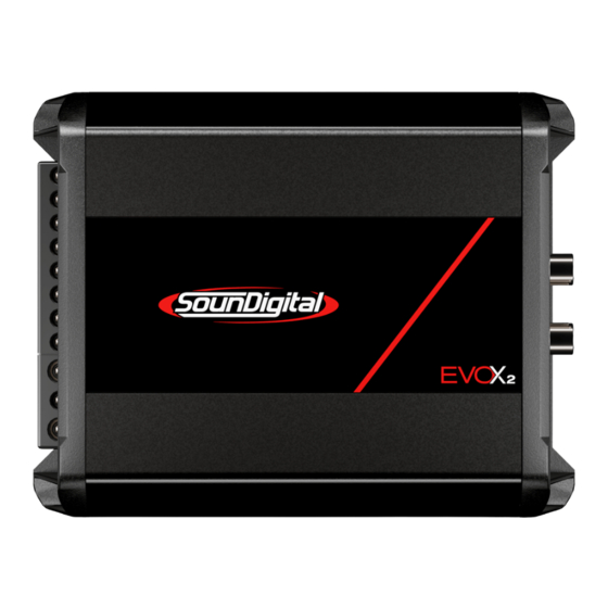
Summary of Contents for SoundDigital 1000.1 EVOX2
- Page 1 OWNER´S MANUAL 1000.1...
-
Page 2: Table Of Contents
Introduction ..........................3 Package contents ....................... 3 Safety instructions ....................... 4 Technologies ® DTM ........................5 I-Power Supply ..................... 5 Vibration Absorption Device..............6 Reduced size....................6 Assembling and Disassembling the plastic cover........... 7 Panels description Audio inputs and controls ..............8 Power inputs and audio outputs ............ -
Page 3: Introduction
PACKAGE CONTENTS ▪ 01 1000.1 EVOX2 Amplifier ▪ 01 Installation quick guide with warranty card ▪ 01 Allen wrench 2.0mm ▪ 01 Allen wrench 2.5mm ▪... -
Page 4: Safety Instructions
SAFETY INSTRUCTIONS To prevent injuries to the user or damage to the amplifier, read all safety instructions written on this manual; If you are insecure about the installation of this equipment, get in touch with our tech support or with a professional specialized in car audio installation; Before proceeding with the installation of any electric equipment on your vehicle, unplug the negative (-) terminal of the battery to avoid fires, injuries or damages;... -
Page 5: Technologies
TECHNOLOGIES ® DYNAMIC THERMAL MANAGEMENT - DTM ALUMINIUM HEATSINK CONDUCTIVE COPPER LAYER ELECTRONIC COMPONENT The DTM* is a dynamic thermal recovery system which always maintains a high efficiency of the amplifier by accelerating the thermal exchange of electronic components with the heatsink. -
Page 6: Vibration Absorption Device
TECHNOLOGIES VIBRATION ABSORPTION ® DEVICE - VAD ® Technology reduces all impact caused by vibration on the electronic circuit board. This can include road vibration and even vibration caused by sound waves, increasing the reliability of our amplifiers. 7.1" REDUCED SIZE technology used amplifiers... -
Page 7: Assembling And Disassembling The Plastic Cover
ASSEMBLING AND DISASSEMBLING THE PLASTIC COVER The plastic covers have the function of finishing and hiding the amplifier fixing screws. To disassembling and assembling them, follow the instructions below. DISASSEMBLING OF THE PLASTIC COVER 1. Carefully pull out the top of plastic cover to release the upside latches, as shown in the picture 1. 2. -
Page 8: Panels Description
PANELS DESCRIPTION 11 10 Blue "Power ON" LED indicator Yellow "Clip" LED indicator "Protection" LED indicator Remote level control connector Variable Bass Boost Control 50Hz (0dB ~ +12dB) Variable Subsonic filter control (5Hz ~ 40Hz) Variable Low Pass filter control (50Hz ~ 500Hz) Low Pass filter ON/OFF switch key Variable Gain control Right Channel... -
Page 9: Power Inputs And Audio Outputs
PANELS DESCRIPTION Negative power supply connector (GND) Remote power supply connector (REM) Positive power supply connector (+12VDC) Positive speaker connector (+) Speakers Output Connectors Negative speaker connector (-) Minimum speaker load allowed (impedance) -
Page 10: Installation Sequence
INSTALLATION SEQUENCE Warning! Mount the amplifier in such a way you have access to the connectors; Ø Install the power cables in the vehicle properly, starting from the battery to the fuse Ø holder or circuit breaker, use the cable with the appropriate size. Make all connections, install fuse holders or circuit breakers, but without placing the fuses or with the circuit breakers in the "OFF"... -
Page 11: Electrical Dimensioning
ELECTRICAL DIMENSIONING AND AUDIO INPUTS ELECTRICAL DIMENSIONING For proper operation of your SounDigital amplifier, you need the proper dimensioning of the electrical system and the cables used. The table below shows the minimum section of GND cables, +12VDC cables and speaker output cables according to the power generated by the amplifier. POWER CABLE (+12VDC) 16mm²... -
Page 12: Sd Rlc And Gain Setting
SD RLC / GAIN SETTING EXTERNAL LEVEL CONTROL - SD RLC (*Not included) The SD RLC is an easy-to-install external level control accessory that allows you to tune the level of SOUNDIGITAL amplifiers that have remote level control. POWER CLIP In SD RLC, you can adjust the amplifier level LEVEL without having to lean over and adjust the gain... -
Page 13: Crossovers Set Up
CROSSOVER AND BASS BOOST SET UP Using Bass Boost The Amplifier Bass Boost setting enables the user to boost the sound intensity at low frequencies of the sound system, where boost intensity can be adjusted. This is a semi-parametric equalizer type circuit with ''Q'' value for the fixed filter, with an intensity boost adjustment from 0 to + 12dB (16 times), and a central frequency adjustment of the filter in 50Hz, making it versatile for several types of sound systems. -
Page 14: Wiring Diagram
WIRING DIAGRAM All RCA inputs must be connected for the channel to work properly. POWER CLIP LEVEL SD REMOTE LEVEL CONTROL* *Sold separately Minimum impedance 1000.1 EVOX2 1Ω 1Ω 1000.1 EVOX2 2Ω 2Ω... -
Page 15: Parameters
TECHNICAL SPECS 1000.1 1Ω 1000.1 2Ω PARAMETERS Power RMS @ 4Ω** 476W 739W Power RMS @ 2Ω** 721W 1000W Power RMS @ 1Ω** 1000W Frequency Response (-3dB) 5Hz ~ 25kHz 5Hz ~ 25kHz Subsonic Filter (12dB/oct.) 5Hz ~ 40Hz 5Hz ~ 40Hz Low Pass Filter (12dB/oct.) 50Hz ~ 500Hz 50Hz ~ 500Hz...

Need help?
Do you have a question about the 1000.1 EVOX2 and is the answer not in the manual?
Questions and answers