Table of Contents
Advertisement
Quick Links
Advertisement
Table of Contents

Related Manuals for AAON RSMD


Summary of Contents for AAON RSMD
- Page 1 RSMD Technical Guide...
- Page 2 ASM01895 www.aaon.com This manual is available for download from www.aaon.com/library AAON AAON is a registered trademark of AAON, Inc., Tulsa, OK. BACnet is a ® ® 2425 South Yukon Ave. registered trademark of ASHRAE Inc., Atlanta, GA. Copeland Scroll™ is Tulsa, OK 74107-2728 a registered trademark of Emerson Electric Co., Saint Louis, MO.
-
Page 3: Table Of Contents
Suction Pressure Transducer Testing ........................24 Copeland Discharge Thermistor Temperature Sensor Testing ................25 Temperature Sensor Testing ..........................26 Head Pressure Transducer ........................... 27 APPENDIX A: CONDENSER OPTIONS ......................28 Condenser Configurations ............................ 28 Module Configurations ............................34 RSMD Technical Guide... - Page 4 Figure 10: ............................32 A2/B2 Condenser Wiring Figure 11: ............................33 TABLES Electrical and Environmental Requirements Table 1: ......................7 RSMD Inputs and Outputs Table 2: ............................10 Navigation Key Functions Table 3: ............................13 Main Screens Table 4: ................................15 Module Screens Table 5: ...............................15...
-
Page 5: Overview
The module is designed for R410-A refrigerant. The RSMD is for units that match all of the following criteria: • One or two circuits; • Compressors may be any mix of fixed, two-step, and digital;... -
Page 6: Dimensions
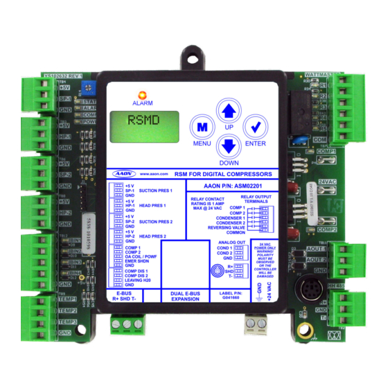
COMP DIS 1 WILL BE BIN4 COMP DIS 2 DAMAGED LEAVING H20 HH485 E-BUS DUAL E-BUS LABEL P/N: G041660 R+ SHD T- EXPANSION TEMP1 TEMP2 TEMP3 4.10 0.75 0.74 NOTE: All dimensions are in inches. Figure 1: RSMD Dimensions RSMD Technical Guide... -
Page 7: Wiring
Please carefully read and apply the following information when wiring the unit controller, RSMD, and any associated module. Correct wiring of the AAON unit controller and its modules is • All wiring is to be in accordance with local and national the most important factor in the overall success of the installation electrical codes and specifications. -
Page 8: Inputs Wiring
HVAC unit. The module is designed for R410-A refrigerant. 2, this page. It is typically required for all VCCX2 applications. The RSMD is connected to the VCCX2 Controller. Up to four Suction pressure transducers are used to measure suction pressure RSMD Modules can be connected, depending on the size of the at the HVAC unit’s DX evaporator coil suction line. -
Page 9: Outputs Wiring
TEMP3 3 Y1 18-30 Connect to VCCX2 Controller Belimo actuator wiring Size transformer for Line Voltage shown. Consult factory for correct total load. other manufacturer wiring RSMD = 18 VA instructions. Figure 3: RSMD Outputs Wiring RSMD Technical Guide... -
Page 10: Inputs And Outputs
INPUTS AND OUTPUTS Inputs/Outputs Map Inputs/Outputs Map See Table 2, this page, for the RSMD inputs and outputs. REFRIGERATION SYSTEM MODULE FOR DIGITAL COMPRESSORS Analog Inputs Suction Pressure 1 Transducer (SP-1) Head Pressure 1 Transducer (HP-1) Suction Pressure 2 Transducer (SP-2) -
Page 11: Inputs And Outputs
INPUTS AND OUTPUTS Inputs and Outputs RSMD - Inputs and Outputs BI3 – Outdoor Coil Temperature / Proof of Water Flow Status +5V – VDC Power This input can be used for the following two options: This output is a 5 VDC output that supplies power to the Suction •... -
Page 12: Sequence Of Operations
Coil Temperature Setpoint. One Digital and One Fixed Compressor If the RSMD has two digital compressors, the first compressor will be locked at 100% and the second compressor will modulate. In units with one digital and one fixed compressor, if the digital... -
Page 13: Lcd Screens
Use this key to adjust setpoints and change configurations. DOWN Use this key to adjust setpoints and change configurations. ENTER Use the ENTER key to navigate through the Main Menu Screen categories. Table 3: Navigation Key Functions RSMD Technical Guide... -
Page 14: Screens Map
H2O FLOW LOW SUCT or if configured 95 PSI for water source heat pump H2O TEMP LOW H2O XX F 37 F If configured for air to air heat pump, the following screen displays DEFR INT 30 MIN RSMD Technical Guide... -
Page 15: Screen Descriptions
Screen Descriptions Main Screens Module Screens Refer to Table 4, this page, when navigating through the LCD Refer to Table 5, this page, when navigating through the RSMD Main Screens. Screens. From the RSMD Screen, press to scroll through <ENTER>... -
Page 16: Table 6: System Status Screens
Defrost interval timer in number of minutes 10 MINS Water flow. Options are: H2O FLOW This screen appears instead of the defrost interval timer If the system is configured with a water source heat pump, Table 6: System Status Screens RSMD Technical Guide... -
Page 17: Table 8: Alarms Screens
No Alarms. This is shown if there are no current alarms. ALARMS EBUS Slave Timeout. This alarm indicates communication has been lost between the RSMD and the controller or other E-BUS EBUS SLV modules that may be connected. This can be the result of a bad cable, a missing cable, or the module not being configured TIMEOUT properly. -
Page 18: Table 9: Alarm History Screens
Appears if configured for water source heat pump. Defrost Interval Setpoint Status. Default is 30 minutes. DEFR INT 30 MIN Appears if the system is configured for air to air heat pump. Table 10: Setpoint Status Screens RSMD Technical Guide... -
Page 19: Protected Screen Map
LCD SCREENS Protected Screen Map Protected Screens Map Refer to the following map when navigating through the LCD Protected Screens. From the RSMD Screen, press twice to get to <ENTER> the SOFTWARE Screen. Then hold the button for five seconds. To scroll through the rest of the screens, press the button. -
Page 20: Screens Map
DIAGNOSTIC SCREENS CONFIG Screen Text Description CONFIG Diagnostic screens COND FAN Condenser Fan. Locked or unlocked LOCKED COND FAN LOCK POS Condenser fan locked position. LOCKED 100% Table 11: Configuration Screens LOCK POS 100% RSMD Technical Guide... -
Page 21: Table 12: Diagnostic Screens
X.XX AOUT-2 V Condenser Signal 2 Force. 0.0 to 10.0 = Active Force Mode. Press the buttons <UP> <DOWN> to increase and decrease the value. BIN 1 Table 12: Diagnostic Screens RSMD Technical Guide... - Page 22 • 3 = C for more information. • 4 = D The number in parentheses is the E-BUS address. • Module 1 is 152 • Module 2 is 153 • Module 3 is 154 • Module 4 is 155 RSMD Technical Guide...
-
Page 23: Troubleshooting
This LED lights up to indicate that 24 VAC power has POWER – been applied to the controller. The RSMD is equipped with LEDs that can be used to verify Binary Input LEDs operation and perform troubleshooting. There are LEDs for communication, operation modes, and diagnostic codes. -
Page 24: Suction Pressure Transducer Testing
Use the voltage column to check the Suction Pressure Transducer 21.19 -6.1 80.94 while connected to the RSMD Module. The VCCX2 and the RSMD 24.49 -4.4 87.16 Module must be powered for this test. Read voltage with a meter set on DC volts. -
Page 25: Copeland Discharge Thermistor Temperature Sensor Testing
3.00 If the voltage is above 4.98 VDC, then the sensor or wiring is “open.” If the voltage is less than 0.38 VDC, then the sensor or wiring is shorted. Table 14: Discharge Thermistor Temperature and Resistance RSMD Technical Guide... -
Page 26: Temperature Sensor Testing
If the voltage is above 4.88 VDC, then the sensor or wiring is “open.” If the voltage is less than 0.05 VDC, then the sensor or wiring is shorted. Table 15: Type III 10 K Ohm Thermistor Sensor Temperature and Resistance RSMD Technical Guide... -
Page 27: Head Pressure Transducer
If there is a problem related to the Head Pressure Transducer, voltage and pressure readings can be taken at the Head Pressure terminal. See Table 16, this page. HEAD PRESSURE TRANSDUCER CHART Voltage Pressure Voltage Pressure Table 16: Head Pressure Transducer Chart RSMD Technical Guide... -
Page 28: Appendix A: Condenser Options
USE < OR > TO CHANGE Wiring See Figure 6, this page, for Default Two Condenser Operations wiring. Select the “2 COND PER RSMD” option on the above Hand Held Service Tool Screen. 24 VAC ONLY YS102632 REV 1 4751... -
Page 29: Figure 7: Single Condenser Per Module Wiring
USE < OR > TO CHANGE • C-BOX Air to Air Heat Pump • C-BOX WSHP Select the “1 COND FOR 1 RSMD” option on the above Hand Held Service Tool Screen. Wiring See Figure 7, this page for Single Condenser per Module wiring. -
Page 30: Figure 8: Single Condenser Per Two Modules Wiring
All relay outputs are normally open Connect to and rated for 24 VAC power only, VCCX2 Controller 1 Amp maximum load. Size transformer for Line Voltage correct total load. RSMD = 18 VA Figure 8: Single Condenser per Two Modules Wiring RSMD Technical Guide... -
Page 31: Figure 9: Single Condenser For Three Modules Wiring
All relay outputs are normally open Connect to and rated for 24 VAC power only. VCCX2 Controller 1 Amp maximum load. Size transformer for Line Voltage correct total load. RSMD = 18 VA Figure 9: Single Condenser for Three Modules Wiring RSMD Technical Guide... -
Page 32: Figure 10: A1/B1 Condenser Wiring
All relay outputs are normally open Connect to and rated for 24 VAC power only, VCCX2 Controller 1 Amp maximum load. Size transformer for Line Voltage correct total load. RSMD = 18 VA Figure 10: A1/B1 Condenser Wiring RSMD Technical Guide... -
Page 33: Figure 11: A2/B2 Condenser Wiring
All relay outputs are normally open Connect to and rated for 24 VAC power only, VCCX2 Controller 1 Amp maximum load. Size transformer for Line Voltage correct total load. RSMD = 18 VA Figure 11: A2/B2 Condenser Wiring RSMD Technical Guide... -
Page 34: Module Configurations
<Fan Cycle Relay Control> the Module Configurations menu in the RSM-D Configuration screen, Fill in the setpoints for Fan Cycle Enable Setpoint, Fan Cycle Deadband, and Fan Cycle Reheat Offset. Both of the above settings can be set per board. RSMD Technical Guide... - Page 35 PARTS: For replacement parts, please contact your local AAON Representative. 2425 So. Yukon Ave • Tulsa, OK • 74107-2728 Ph: (918) 583-2266 • Fax: (918) 583-6094 AAON P/N: G039810, Rev. G Created in the USA • © December 2022 AAON All Rights Reserved...
Need help?
Do you have a question about the RSMD and is the answer not in the manual?
Questions and answers