Table of Contents
Advertisement
Advertisement
Table of Contents

Related Manuals for Dahua Technology DHI-IPMECD-2031-RM1515-T20

Summary of Contents for Dahua Technology DHI-IPMECD-2031-RM1515-T20
- Page 1 Boom Barrier User’s Manual V1.0.0 ZHEJIANG DAHUA VISION TECHNOLOGY CO., LTD.
-
Page 2: Foreword
Description Variable frequency boom barrier with 3 m (9.84 ft) folding arm (at the right side), each of the two sections of the DHI-IPMECD-2031-RM1515-T20 arm is 1.5 m (4.92 ft) Opening/closing time: 2 s Variable frequency boom barrier with 3 m (9.84 ft) folding... - Page 3 User’s Manual Variable frequency boom barrier with 3 m (9.84 ft) DHI-IPMECD-2032-LM30-T10 straight arm (at the left side) Opening/closing time: 1 s Variable frequency boom barrier with 3.5 m (11.48 ft) DHI-IPMECD-2032-RM35-T15 straight arm (at the right side) Opening/closing time: 1.5 s Variable frequency boom barrier with 3.5 m (11.48 ft) DHI-IPMECD-2032-LM35-T15 straight arm (at the left side)
- Page 4 User’s Manual Signal Words Meaning Indicates a high potential hazard which, if not avoided, will result in death or serious injury. Indicates a medium or low potential hazard which, if not avoided, could result in slight or moderate injury. Indicates a potential risk which, if not avoided, may result in property damage, data loss, lower performance, or CAUTION unpredictable result.
-
Page 5: Important Safeguards And Warnings
User’s Manual Important Safeguards and Warnings This chapter introduces the contents covering proper handling of the Barrier, hazard prevention, and prevention of property damage. Read these contents carefully before using the Barrier, comply with them when using, and keep the manual well for future reference. Power Requirements ... - Page 6 User’s Manual In case of power failure, turn off the power first, and then swing the barrier arm to a vertical position with the handwheel. When the Barrier is delivered, the length of the barrier arm and the balance spring have been matched to a balanced status, and there is no need to change the length and weight of the barrier arm.
-
Page 7: Table Of Contents
User’s Manual Table of Contents Foreword ..............................I Important Safeguards and Warnings ....................IV 1 Introduction ............................1 Overview ............................1 Features ............................1 2 Structure ..............................3 Appearance ........................... 3 Dimensions ........................... 4 Components ..........................5 3 Installation .............................. 6 Installation Position Requirements .................... -
Page 8: Introduction
Introduction Overview The Barrier uses digital variable frequency servo controller, allowing stepless speed control of the drive motor without loss of output torque. The opening and closing time of the Barrier can be set from 1 s to 4 s and from 2 s to 6 s respectively, and the Barrier can be controlled by a remote control, with a maximum distance of 50 m. - Page 9 User’s Manual Manual Opening, Closing and Locking of Barrier Arm during Power Failure During power failure, manually rotate the manual handle or locking handle to operate the barrier arm. The barrier arm can be locked at any position between horizontal and vertical positions. When the barrier motor stops, swipe down the locking button on the manual handle or locking handle to lock the Barrier.
-
Page 10: Structure
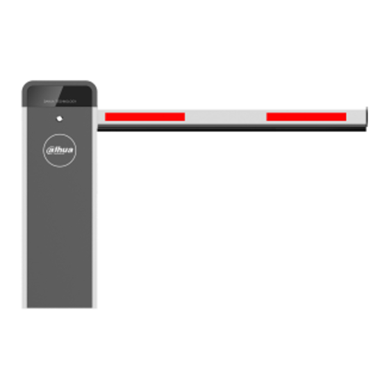
Structure Appearance Straight Arm Barrier Figure 2-1 Straight arm barrier Folding Arm Barrier Figure 2-2 Folding arm barrier... -
Page 11: Dimensions
User’s Manual Dimensions Figure 2-3 Dimensions (mm [inch]) -
Page 12: Components
User’s Manual Components Figure 2-4 Components Table 2-1 Description of components Description Description Cover Lever Spring rod Base Driven counterweight rocker arm Motor Mainshaft Driving rocker arm Connecting rod Casing Counterweight spring Controller Power supply Ground Door — —... -
Page 13: Installation
Installation Installation Position Requirements Conspicuous position. The barrier arm surface faces outward (intersection). The bottom of the Barrier must be on the same plane as the road. After confirming the position, build the barrier foundation based on the site conditions. Cast-in-place foundation must be built on the non-concrete ground. -
Page 14: Installing Barrier Arm
User’s Manual Figure 3-2 Install casing Table 3-1 Description of installation components Description Description Casing of the Barrier Two metal plates Four M12 × 120 anchor bolts Concrete foundation or pavement Two sets of M12 nuts, spring gaskets — — and flat gaskets Installing Barrier Arm Take out barrier arm accessories, and then install the straight arm or the folding arm shown as... - Page 15 User’s Manual Figure 3-3 Installing straight arm Table 3-2 Description Description No. Description Four M8 × 16 countersunk bolts Lever Two sets of M8 × 120 bolts, flat Straight arm gaskets and nuts Figure 3-4 Installing folding arm...
-
Page 16: Adjusting Barrier Arm Length
Table 3-3 Description Description Description Metal plate Screw Lever Rear cover — — Adjusting Barrier Arm Length The operating parameters are adjusted before delivery according to the required barrier arm length. When the Barrier is delivered on site, you need to adjust the mechanical balance of the Barrier again to keep the barrier arm in horizontal state. - Page 17 User’s Manual Description Description Traffic light power input IR input Traffic light output RS-485 communication Figure 3-6 Control board wiring Table 3-5 Description of control board Description Description Power off when arm rises 24V DC power input Radar loop IN power output Radar loop Reserved Reserved...
- Page 18 User’s Manual Loop Anti-smashing/Arm Falling The falling barrier arm will immediately rise to vertical position if the LOOP1 signal is triggered, during which the arm will not fall down until the loop input returns to normal state. This function is not available when the angle between the arm and water level smaller than 9°. Rising Priority If a vehicle is about to pass when the barrier arm falls, the security guard can press the rising signal on the remote control to make it immediately rise to the opening state, avoiding the...
-
Page 19: Control Board Settings
Control Board Settings There are three buttons (SET, +, -) on the control board. During normal operation, + is manual rising button; - is manual falling button; the LED displays the position state value of the barrier arm (vertical 0 and horizontal 95) or error code in real time. When configuring the parameters, they are recorded after the barrier arm rises and the LED displays 0. - Page 20 User’s Manual Function Description number Relay settings: 0/10-RL1: Outputs red and green hidden by default. You light signals; 1/11-RL1: Outputs signals when the need to press and hold barrier arm is operated; 0/1-RL2: Loop output; SET for 6 seconds in 10/11-RL2: Rising to position output;...
-
Page 21: Maintenance And Operation
Maintenance and Operation It is recommended to inspect the following items every three months: Screw looseness Open the upper cover of the Barrier, and control the barrier arm up and down to inspect whether the screws of the spring rod are loose and whether the retainer rings of the connecting rod are in place. - Page 22 User’s Manual Figure 5-2 Cushion rubber gaskets Table 5-2 Description of screw looseness Description Cushion rubber gaskets Spring balance Temporarily turn off the power, and keep the barrier arm at 40°–45° from the horizontal plane to check whether the barrier arm can be still and balanced. If not, adjust the spring tightness.
-
Page 23: Common Faults And Troubleshooting
User’s Manual Common Faults and Troubleshooting Error Code Table 6-1 Error code description Error Code Description Pulse angle gauge or motor error code. Rising input error code: Continuous input short circuit for more than 10 seconds is considered as an error. Falling input error code: Continuous input short circuit for more than 10 seconds is considered as an error. - Page 24 User’s Manual Possible Causes Solutions If the barrier arm moves slowly, but the control board LED does not display the Replace the angle encoder of the movement angle value, it motor. means that the angle encoder of the motor is damaged. The barrier arm is not tightly Check and fix the barrier arm again.
-
Page 25: Appendix 1 Cybersecurity Recommendations
User’s Manual Appendix 1 Cybersecurity Recommendations Cybersecurity is more than just a buzzword: it’s something that pertains to every device that is connected to the internet. IP video surveillance is not immune to cyber risks, but taking basic steps toward protecting and strengthening networks and networked appliances will make them less susceptible to attacks. - Page 26 User’s Manual Change Default HTTP and Other Service Ports We suggest you to change default HTTP and other service ports into any set of numbers between 1024~65535, reducing the risk of outsiders being able to guess which ports you are using. Enable HTTPS We suggest you to enable HTTPS, so that you visit Web service through a secure communication channel.
- Page 27 User’s Manual Establish the 802.1x access authentication system to reduce the risk of unauthorized access to private networks. Enable IP/MAC address filtering function to limit the range of hosts allowed to access the device.
- Page 28 User’s Manual Declarations By connecting the product into Internet, you have to bear related risks on your own account, including but not limited to those related to cyber attacks, hacker attacks, and virus infections. It is advised to enhance the protection for your network data, device data, and personal information.
Need help?
Do you have a question about the DHI-IPMECD-2031-RM1515-T20 and is the answer not in the manual?
Questions and answers