
Summary of Contents for CHIYU BF-1010
- Page 1 BF-1010 User Manual Document Version 2.0 Web Version 1.8, Jan 15 2018 Firmware Version 1.11.09, Oct 3 2019...
-
Page 2: Table Of Contents
Feature of BF-1010 ....................3 Ⅲ、Login WEB ........................4 Preparation ......................4 How to search BF-1010 ..................4 Use a web browser to enter the BF-1010 Web configuration interface....7 Ⅳ、Web function description....................8 Basic Setup......................8 1、Network Setting ....................8 (1) STATIC IP ......................8 ... - Page 3 Function Description................22 I/O Normal State/Trigger Mapping Setup ............23 Function Description................23 VMS Setting......................24 Function Description................24 Sensor Threshold ....................25 Function Description................25 I/O Auto Report Setup ..................26 Function Description................26 E-Mail Alert ......................27 Function Description................27 ...
-
Page 4: Bf-1010 Instruction
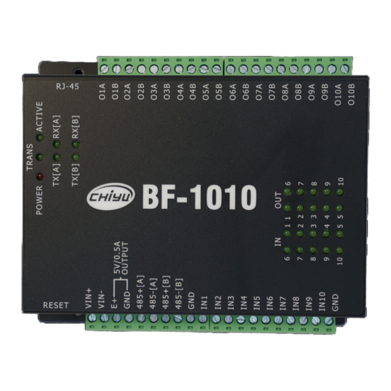
- BF-1010 Instruction - Ⅰ 、 Hardware Introduction Appearance Specifications Name Specifications 16 Bits, 100MHZ Memory 512KB Flash & 1MB SDRAM Setting interface Web management interface Input point 1. 10 groups of digital input points 2. Interconnection via terminal block 3. -
Page 5: Endpoint Description
Endpoint description... -
Page 6: Ⅱ、 Product Description
The files backed up for security reasons will be stored in an encrypted manner. BF-1010 has a total of 10 groups of DI / 10 sets of DO. The simple web page setting method allows users to avoid programming background. -
Page 7: Ⅲ、Login Web
The computer can establish a physical connection with the BF-1010. The computer and the BF- 1010 must be in the same domain at the same time. The BF-1010 has been installed and powered If the default IP address (192.168.0.125) of BF-1010 has been adopted by other devices, you should turn off the other devices until the setting is completed and assign a new IP address to BF- 1010. - Page 8 3. After the IP Search window appears, it will display all BF-1010 currently in the domain to which it belongs. The window will display BF-1010's Terminal ID, Model Name, IP Address, Subnet Mark, Gateway, Mac Address, Software IP, click BF-1010 displayed in...
- Page 9 6. After the modification is completed, the IP address of BF-1010 has already conformed to the domain to which it belongs. If you want to enter the web of BF-1010 at this time, there are the following two methods:...
-
Page 10: Use A Web Browser To Enter The Bf-1010 Web Configuration Interface
IP address of BF-1010. Set the computer IP to the IP address of the same network segment as BF-1010. If the computer uses a fixed IP address, the address must be between 192.168.0.1 ~ 192.168.0.124 or 192.168.0.126 ~ 192.168.0.254. -
Page 11: Ⅳ、Web Function Description
(1) STATIC IP Function Description IP Address: Set the IP address of BF-1010, the default value is 192.168.0.125 Subnet mask: Set the Subnet mask of BF-1010, the default value is 255.255.255.0 Gateway: Set the default Gateway of BF-1010, the default value is 192.168.0.254... -
Page 12: Dhcp Client
(2) DHCP CLIENT Function Description Host Name (optional): Enter host name, the default is BF-1010, non-required field. -
Page 13: Pppoe
1. Set the idle disconnection time (seconds), the default value is 0 seconds, the range is 0 ~ 4294967295 2. If you want to keep BF-1010 and ISP connected at any time, you must set this value to 0, otherwise, if there is nodata transmission exceeding the set time, it will automatically... -
Page 14: Network Operation Mode
Network operation mode Data PORT 1 (1) TCP Server... -
Page 15: Function Description
1. Set the idle disconnection time, the default value is 0 seconds, the range is 0 ~ 32768 2. When you want to keep the BF-1010 connected to the monitoring at all times, you must set this value to 0, otherwise the segment connection will be automatically cut when no data is transmitted... -
Page 16: Tcp Client
(2) TCP Client Function Description Destination IP Address 1: Set the remote IP address and port number of the first group, the range of PORT is 0 ~ 65535, the default is 50000. Destination IP Address 2: Set the remote IP address and port number of the second group, the range of PORT is 0 ~ 65535, the default is 50000. -
Page 17: Udp Client
(3) UDP Client Function Description Destination IP Address 1: Set the remote IP address and port number of the first group, the range of PORT is 0 ~ 65535, the default value is 50000. Destination IP Address 2: Set the remote IP address and port number of the second group, the range of PORT is 0 ~ 65535, the default value is 50000. -
Page 18: Data Port 2
Set the idle disconnection time, the default value is 30 seconds, the range is 0 ~ 32768. When you want to maintain the connection between BF-1010 and the monitoring terminal at any time, you must set the value to 0, otherwise when there is no data on the line and the transmission exceeds the set time, the connection will be automatically disconnected. -
Page 19: Tcp Client
(2) TCP Client Function Description Destination IP Address 1: Set the remote IP address and port number of the first group, the range of PORT is 0 ~ 65535, the default value is 50001. Destination IP Address 2: Set the remote IP address and port number of the second group, the range of PORT is 0 ~ 65535, the default value is 50001. -
Page 20: Udp Client
(3) UDP Client Function Description Destination IP Address 1: Set the remote IP address and port number of the first group, the range of PORT is 0 ~ 65535, the default value is 50001. Destination IP Address 2: Set the remote IP address and port number of the second group, the range of PORT is 0 ~ 65535, the default value is 50001. -
Page 21: I/O Port
Set the idle disconnection time, the default value is 30 seconds, the range is from 0 ~ 32768, when you want to maintain the connection between BF-1010 and the monitoring terminal at any time, you must set this value to 0, otherwise, when there is no data transmission on the connection exceeding the set time, it will automatically disconnect. -
Page 22: Tcp Client
(2) TCP Client Function Description Destination IP Address 1: Set the remote IP address and port number of the first group, the range of PORT is 0 ~ 65535, the default value is 50002 Destination IP Address 2: Set the remote IP address and port number of the second group, the range of PORT is 0 ~ 65535, the default value is 50002 Destination IP Address 3: Set the remote IP address and port number of the third group, the range of PORT is 0 ~ 65535, the... -
Page 23: Udp Client
(3) UDP Client Function Description Destination IP Address 1: Set the remote IP address and port number of the first group, the range of PORT is 0 ~ 65535, the default value is 50002 Destination IP Address 2: Set the remote IP address and port number of the second group, the range of PORT is 0 ~ 65535, the default value is 50002 Destination IP Address 3: Set the remote IP address and port number of the third group, the range of PORT is 0 ~ 65535, the... -
Page 24: Serial Operation Mode
Function Description Baud Rate: 1. Set the baud rate of BF-1010 serial port number 1. The parameters that can be set are: 1200, 2400, 4800, 9600, 19200, 38400, 57600, 115200, 230400 and others. 2. After selecting Others, you must enter a custom baud rate in the User Defined space. -
Page 25: Port 2
Function Description Baud Rate: 1. Set the baud rate of BF-1010 serial port number 1. The parameters that can be set are: 1200, 2400, 4800, 9600, 19200, 38400, 57600, 115200, 230400 and Others 2. After selecting Others, you must enter a custom baud rate in the User Defined space. -
Page 26: I/O Normal State/Trigger Mapping Setup
I/O Normal State/Trigger Mapping Setup This page can set which OUTPUT to be triggered according to the change of INPUT signal (LOW and HIGH), and can set the duration of OUTPUT (Latch Time) to determine the length of the relay trigger , if set to 0, the state of OUTPUT trigger can be released when INPUT status is restored to normal. -
Page 27: Vms Setting
VMS Setting Function Description NX Server IP: If you will use with Network Optix, please fill the NX Server IP NX Server Port: Fill the NX Server Port, the default is 7001 User name: It’s the account number to login NX, the default is admin Password: It’s the password to login NX, the default is admin12345 NX Alarm Source:... -
Page 28: Sensor Threshold
Sensor Threshold Function Description Trigger By: It can select Temperature, Humidity or CO2. Trigger Status: It can set High, Low or disable, the default is disable. Trigger Value: It can set the Trigger Value for Temperature, Humidity or CO2 here. VMS Alarm Source: It can select the Alarm Source of Sensor. -
Page 29: I/O Auto Report Setup
I/O Auto Report Setup Function Description Auto Report: Select to enable or disable the automatic report I / O function, the default value is off. Interval Time: Set the interval time for automatic report I / O, can be set from 0 to 65535 seconds, the default is 0 seconds. -
Page 30: E-Mail Alert
E-Mail Alert Function Description E-mail Alert: Set whether to enable or disable the alarm mail, the default value is off Domain Name (optional): Domain name setting, up to 59 characters can be set, the default value is blank (optional fields) SMTP Mail Server: Set the SMTP server. -
Page 31: System Clock Setup
System Clock Setup Function Description There’re two ways to set System Clock: 1. Set the Time Server to Enable and set the Time Zone to the correct area. 2. Set the Date and Time, then Apply it. -
Page 32: System Log
System Log Function Description Date: Display the date when the system record occurred, in the order of month / day / year Time: Display the time when the system record occurred, the order is hour / minute / second Description: Display system recorded description... -
Page 33: Management
Management 1、Device Administration Setting... -
Page 34: Function Description
Display and set the IP address of the reserved management device, the default value is 192.168.200.200 Device Hostname: Set the name of the device host, the default is BF-1010 Device Location: Set the location name of the device host, the default is blank... -
Page 35: 2、System Status Monitor
2、System Status Monitor... -
Page 36: Function Description
50000/50001 MAC Address Display MAC Address of BF-1010 IP Address Display IP address of BF-1010, the default is 192.168.0.125 Subnet mask Display Subnet mask of BF-1010, the default is 255.255.255.0 Default Gateway Display default gateway of BF-1010, the default is 0.0.0.0... -
Page 37: 3、I/O Status
Feature Description INPUT Status Display status of BF-1010 INPUT 1~ INPUT 10, the default is LOW OUTPUT Status Display status of BF-1010 OUTPUT 1 ~ 10, the default is OPEN It can click SHORT-1 ~ 10 or OPEN-1 ~ 10 to control the OPEN or... -
Page 38: 4、Backup & Restore Configuration
4、Backup & Restore Configuration Function Description Backup: After execution, the current system settings can be saved as a backup file and stored in the hard disk. The extension of the stored file is .cfg Restore: Browse to select the backup file (.cfg), and restore the system settings after running Restore... -
Page 39: 5、Firmware Upgrade
5、Firmware Upgrade Function Description Feature Description Please select a file to upgrade After browsing and selecting the firmware, it can upgrade the firmware after executing UPGRADE The power supply must be stable during the upgrade process, otherwise it will cause irreparable errors. ... -
Page 40: 6、Ping
Function Description Feature Description Source IP Address Display IP address of BF-1010 Destination IP Address Enter the IP address of the remote connection host Packet Number Set to sent the number of PING packets, the range is 1 ~ 4, the default is 4...
Need help?
Do you have a question about the BF-1010 and is the answer not in the manual?
Questions and answers