Table of Contents
Advertisement
U
S
E
A
U
S
E
A
S
T
O
N
E
S
T
O
N
E
R
S
G
R
S
G
Frazione Cavallotta – Via Costigliole, 4 – S.P. 156 – 12038 SAVIGLIANO (CN) - Italy
Tel (+39) 0I72 – 377167 Fax (+39) 0172 – 377014
www.massanosnc.com
"With Declaration of Conformity "(CE)
Carefully read the manual before using the machine
N
D
M
A
I
N
D
M
A
I
B
U
R
I
E
R
B
U
R
I
E
R
T
T
–
R
S
L
–
–
R
S
L
–
R
S
R
S
E-mail: info@massanosnc.it
N
T
E
N
A
N
N
T
E
N
A
N
W
I
T
H
R
E
W
I
T
H
R
E
y
p
e
:
y
p
e
:
R
S
C
–
R
R
S
C
–
R
E
P
L
U
S
E
P
L
U
S
C
E
B
O
O
C
E
B
O
O
A
R
R
O
L
L
A
R
R
O
L
L
S
E
–
R
S
S
E
–
R
S
K
K
E
R
E
R
F
F
Vers. 2015
Advertisement
Table of Contents

Related Manuals for Massano ROTOSTONE RSG

Summary of Contents for Massano ROTOSTONE RSG
- Page 1 – – – – – – – – Frazione Cavallotta – Via Costigliole, 4 – S.P. 156 – 12038 SAVIGLIANO (CN) - Italy Tel (+39) 0I72 – 377167 Fax (+39) 0172 – 377014 www.massanosnc.com E-mail: info@massanosnc.it “With Declaration of Conformity “(CE) ...
- Page 3 MASSANO s.n.c. Frazione Cavallona – SAVIGLIANO (CN) - Italy Tel (+39) 0I72 – 377167 Fax (+39) 0172 – 377014 www.massanosnc.com E-mail: info@massanosnc.it Holder of the technical dossier at head office Company: Diego Massano certifies under its responsibility that the machine: Type : ..………………………………..
-
Page 4: Table Of Contents
INDEX REMARKS ........................7 GENERAL INFORMATION ..................7 2.1 INFORMATION ABOUT THE BOOK ---------------------------------------------------------------------------------- 7 2.2 INFORMATION ABOUT THE MACHINE ----------------------------------------------------------------------------- 8 2.2.1 Machine identification ........................ 11 2.2.2 Use of the machine..………………………………………………………..………………………….12 TECHNICAL FEATURES ................... 13 3.1 Machine parts and technical data ------------------------------------------------------------------------------------ 13 33.2 Technical data ------------------------------------------------------------------------------------------------------------- 14 ………………………………………………………………………………………………………... - Page 6 Massano Snc and your dealer are available for any information regarding the running of the machine and also provide original spare parts to ensure its perfect fit in case of replacement.
-
Page 7: Remarks
Massano snc and it must be associated with the machine until its destruction. If you don’t receive the book or you lose it, we strongly suggest you to ask Massano snc for a copy. Our offices will send it as soon as possible. -
Page 8: Information About The Machine
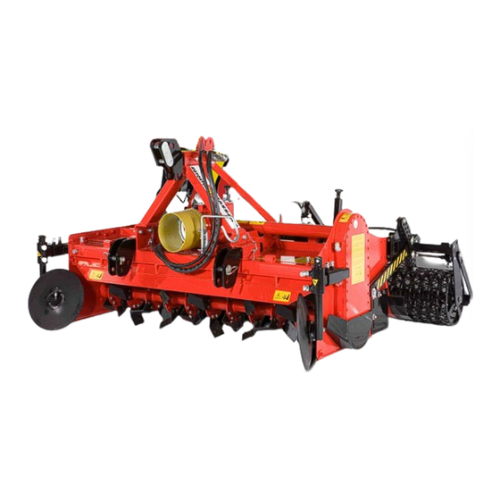
We strongly suggest you to use only original spare parts and accessories. The use of non-original parts could invalidate the guarantee, be dangerous and risk life and reduce the performance of the machine. INFORMATION ABOUT THE MACHINE This manual describes the operating principle of the stone burier for stones and vegetable residues type ROTOSTONE. - Page 9 This three point (A) mounted machine, when hitched to a tractor of appropriate horsepower, has proven to be ideal for the elimination, in one pass, of stones and vegetable residues on the surface. The heart of the machine is the blade rotor (B), composed of specifically designed blades. Whose counter-rotation, throw stones, dirt, weeds an debris against the selection grill (C).
- Page 10 development and maintenance of golf courses, remediation and inter-row weeding:vineyards- orchards-nurseries. The Stone burrier can mount two types of rotors : 1° TYPE - ROTOSTONE - Used to bury stones, vegetables residues such as roots, harvest remains and small sticks by means of specially designed tiller blades that, in the soil, pull out the stones and throw them against the selection grill.
-
Page 11: Machine Identification
2.2.1 Machine identification On the frame of the machine are fixed the EEC brand and the identification label giving manufacturer’s data, model, serial n., production year and weight of the machine. Location of the EEC plate on the machine The information shown on the identification plate are necessary to request spare parts. It is absolutely forbidden to remove and/ or modify all or part of the data specified on the identification plate of the machine. -
Page 12: Use Of The Machine
2.2.2 Use of the machine The following are the main rules for the use of the Stone Burier: o Observe and apply carefully the instructions for adjusting the height of the machine from the ground. It is strictly forbidden to stop within the range of machine’s working up to 50 meters. -
Page 13: Technical Features
TECHICAL FEATURES The Stone Burier, with different power features, has been designed to work in the heaviest conditions minimizing the possibility of damage and wear. This feature is guaranteed by the use of high quality materials during all stages of machine’s construction and can reduce amortization costs to a minimum. -
Page 14: Technical Data
TECHNICAL DATA... -
Page 15: Accessories
Hydraulic seeder connection: allows to assemble any seeder to the Stone Burier very easily. The hydraulic connection raises the equipment bringing it above the machine. MASSANO snc suggests to use seeder with a weight lower than 1200 kg and with a length lower than 220 cm. -
Page 16: Noise Level
5 PACKAGING AND DELIVERY It is not necessary to pack the machine. It is usually supplied by MASSANO snc ready to be used previuosly adjusted for work and is shipped in this condition. ATTENTION! In order to lift the machine use safety hooks and ropes or chains of adequate capacity. -
Page 17: Storage
ATTENTION! Before lifting the machine, make sure that the used device (crane, bridge crane, forklift truck, etc ..) is sufficiently sized in relation to the mass of the machine you have to move (Mass of the unit, see section 3.2 "Technical data") Do not move the machine without checking its perfect stability during the operations you have to carry out. -
Page 18: Restoration After A Long Storage
Check if there are some rusted metal parts, missing pictograms, structural deformations or oil leaks. In case you notice the presence of one or more of these situations, act in the most appropriate way. If necessary, contact MASSANO Snc or its dealer; ... -
Page 19: Safety Regulations
Company. Every change you bring the machine that is not previously authorized by the manufacturer (in writing) releases MASSANO Snc from all civil and criminal liabilities towards peole and/ or things. WARNING! MASSANO Snc is not responsible for possible damages caused by a not foressen or inadequate use of the machine. -
Page 20: Safety And Anti- Industrial Injuries Regulations
MASSANO Snc authorized staff (manufacturer technicians or dealer mechanics) Massano s.n.c. cannot foresee all possible circumstances that are able to cause dangers. Warnings contained in this book and on the machine are not complete. o In addiction to the warnings included in this book, please observe all general safety and anti- industrial injuries regulations. - Page 21 Check the hydraulic pipes wear. Replace them if they are deteriorated or at least every six years, contacting Massano Snc or one of its authorized dealer. o When the machine is disconnected from P.t.o., put the hydraulic pipes and the drive shaft on...
- Page 22 Incorrect use of the machine or employment by non-trained staff ; Heavy lacks in the expected maintenance; Non- authorized changes or interventions by Massano Snc; Use of non-original spare parts or not specific spare parts for this type of machine;...
-
Page 23: Symbols' Graphic Representation
7.2 SYMBOLS’ GRAPHIC REPRESENTATION The symbols below attract the operator’s attention on dangerous situations that may occur and give you safety indications. The following symbols on the machine specify dangers or duties that the user must keep to. SYMBOL DESCRIPTION 1. - Page 24 9. ATTENTION- Danger of getting caught and dragging. Do not bring hands near to the drive shaft when it is working. 10. ATTENTION- Do not stop between the tractor and the machine. 11. ATTENTION- Do not remove or open protection casings until the chains are completely steady.
-
Page 25: Location Of Pictograms On The Machine
7.3 LOCATION OF PICTOGRAMS ON THE MACHINE Make sure that the safety pictograms on the machine are readable. Clean them using a cloth, soap and water. Replace damaged labels and stick on the new ones in the correct place, WARNING! as shown below. -
Page 26: Installation And Adjustments
The three-point hitch of the tractor and of the machine must match perfectly or be adapted by contacting MASSANO Snc. In the area of the rear lift arms of the tractor there is a risk of injury due to crushing and cutting points: connect and disconnect the machine only on firm and flat surfaces. -
Page 27: Check Of Tractor's Lifting Capability And Stability
8.2 CHECK OF TRACTOR’S LIFTING CAPABILITY AND STABILITY Before connecting the machine to the tractor, check the lifting capability and stability of the tractor, using the following formula and if it is necessary (and if it is possible) previously apply the ballasts. -
Page 28: Connection To The Tractor's Three-Points Hitch
8.3 CONNECTION TO THE TRACTOTR’S THREE-POINTS HITCH The stone-burier can be connected on tractors equipped with three-point hitch. Light the working area in case of poor visibility and make sure that there is nobody within 5 mt from the hitching point. Arrange the lifting bars of the tractor by opening the hooks of connection system in order to connect the machine (See... - Page 29 A Distance Place the lifting bars of the tractor to obtain a distance from the ground equal to the distance of the P.t.o. exit. Measure, with a bar, the distance between the centre of the lower bars’ hooking point of the lifting system and the final part of P.t.o.
- Page 30 If the Pto shaft is too long, first of all fairly cut the outer plastic protection tubes (1) and then the inner metal tubes (2). Then deburr and lubricate (3). ATTENTION: when the cardan shaft is completely open, the two tubes must overlap at least 1/3 of their length, while when it is in position of minimum length there must be present 10 cm of free light.
-
Page 31: Adjustment Of Cardan Shaft With Clutch
8.3.1 Adjustment of the cardan shaft with clutch The cardan shaft can have a safety clutch in order the machine does not receive overloads or excessive efforts during its use which are dangerous for the transmission components. The clutch is pre-adjusted to an average force. If during use you notice an excessive slipping of the device, tighten of a turn at a time the nuts that hold the springs (see point A). - Page 32 After adjusting the drive shaft: Check the asembling direction of the cardan shaft according to the information stamped on its protection and fix the universal joint ½ "side machine" connecting it to the p.t.o. gearbox of the bed former. Tighten with a hexagonal wrench ensuring the two screws to the output shaft, thereby locking the drive shaft of the machine.
- Page 33 Connect the machine to the tractor using the lower arms linking the tractor with the connection points of the machine, then connect them and secure them (see use and maintenance book of the tractor). Remove the drive shaft from the support hooking the drive shaft to the stub shafts of the tractor, carefully checking the correct...
- Page 34 With the stone burier in flat position and the stub shafts of the tractor P.t.o. and gearbox at the same height, check that the complete Pto shaft is extended 2”- 4” from its closed length when connected to allow the P.t.o. halves to telescope in and out during lifting by the tractor.
- Page 35 Check carefully that, while lifting the machine, the front discs do not bump against the wheels of the tractor. In the case the disc touch the trasctor’s wheels move away the connection points of the machine. To properly move away the connection points of the machine, disconnect the machine, remove the locking pins of the hitch pins, remove the pins and reposition...
- Page 36 Once you have finished to connect and adjust the machine, lock the horizontal movement of the bars of the lift acting on the special tighteners parallel to the tractor. This arrangement should be put in place to prevent any crosswise movement of the machine, that is dangerous for the stability of the machine - tractor.
-
Page 37: Transport By Road
9 TRANSPORT BY ROAD ATTENTION! For road transport it is necessary to: - Make sure that the tractor used for road transport is properly certified and have all the documents to circulate on road. - Have a valid driving license for the tractor used on road. - Check the cleanliness of the tires before going on public roads. -
Page 38: Before Starting Work
10 BEFORE STARTING WORK Before using the machine you must adjust it allowing a right use of the machine and improving the quality of the work done by it. 10.1 SIDE DISCS’ ADJUSTMENT Follow the instructions below: • Release of the lock nut, •... - Page 39 And the bolts for the front adjustment. For a correct adjustment and side discs use follow these basic rules: Slide out, from the transmission side, the disc support arm about 5-6 cm, securing it subsequently through the tightening of bolts and clamping counter.
- Page 40 To adjust properly set the side disc to a working depth (H) 1” inch lower than the line (O). During work this distance may change due to the needs. Make sure that the disc is rotated so you can create a furrow at least as wide as the width of the chain cover (A).
-
Page 41: General Machine Adjustments
10.2 GENERAL MACHINE ADJUSTMENTS Before using the machine check some important points that determine the correct operation and reduced stress on its parts during work. 10.2.1 Adjustment of the parallelism with the ground Lift the stone burier from the ground about 14 inches and verify that it is parallel to the tractor and, consequently, to the ground on which it operates. -
Page 42: Adjustment Of The Distance With The Tractor
10.2.2 Adjustment of the distance from the tractor The machine is equipped with special brackets for connection to the tractor that allow, through adjustment, to change the distance between the machine and the wheels of the tractor to avoid possible contacts during the lifting for the transport or during work. The adjustment of the connecting brackets’... -
Page 43: Adjustment Of The Rear Roller Position
10.2.3 Adjustment of the rear roller position The rear roller allows the adjustment of machine’s working depth. It allows, through the positioning of the locking pins in the perforated flanges, to be locked or bound in certain positions that, during work will determine the position of the machine as to the ground. -
Page 44: Adjustment Of The Rear Fins (Leveling Bar)
Insert the lower check pin in the desired position and lock it with the suitable epingle.The positioning of the safety pin in the first free hole below the supporting bar of the roller fully bind the rear roller’s movement, both during lifting and during lowering of the machine. -
Page 45: Adjustment Of The Side Straps
10.2.5 Adjustment of the side straps The side straps (A) on the machine fill the furrows previously opened by the front discs in order to allow the passage of machine’s skids and its casing cover. The filling of the furrow takes place thanks to the ground worked by the machine which, through the adjustable positioning or the side straps’... -
Page 46: Adjustment Of The Selection Grill
10.2.6 Adjustment of the selection grill The adjustment of the rear selection grill by means of the crank must be carried out according to the degree of humidity of the soil and to the working depth. When the ground is dry the grill must be left perpendicular to it (closed position), in this way its function of sieve will allow to separate stones, clods and vegetable residue from the fine soil. -
Page 47: Adjustment Of The Scraper
10.2.7 Adjustment of the scraper Perforated roller The perforated roller, available for any stone burier, allows to obtain an extremely soft excellent seed bed, perfect for transplanted in cube crops, or for sowing small seeds such as grass, salad, carrots, onions, etc. The roller, made of a particular smooth grill, allows to work also on wet ground thanks to the use of a scraper adjustable by means of a pressure screw, as you can see in the picture. -
Page 48: Use Of The Machine
USE OF THE MACHINE ATTENTION! Use always appropriate personal protective devices (safety shoes, work gloves, casing for hearing protection and anti- dust mask). Before using the machine make sure that there are no people or animals within 50 metres. Before starting work, you must adjust the machine, in order to obtain an excellent working position (See section 10). - Page 49 Check also that the P.t.o. rotation of the tractor is the same as the machine, see the label. The rear door, in addition to contain clods already worked by blades, allows you to have a well- leveled and homogeneous surface after tillage. If you lift the hood, the equipment cannot break the clods and the soil is not flat and homogeneous.
-
Page 50: Rear Roller Positioning
11.1 REAR ROLLER POSITIONING During the use of the machine in open field, the rear roller (if adjustable) must be positioned in order to be able to completely remove the created edge lines. To do this, the roller must maintain a central position, stretching out in equal measure from both sides of the machine. -
Page 51: Maintenance
MAINTENANCE Following you can find the suggested criteria for the routine maintenance of the machine, based on our business experience, advices and suggestions of our customers. These criteria are not exhaustive, they can be further integrated with the cooperation of the customers we thank in advance. -
Page 52: Every 8 Hours Work
Every 8 hours work 12.1.1 Check the tightness of the bolts securing the blades, the flanges and the rotor Grease the side house bearing of the rotor Grease roller bearings Grease the side discs house bearing (if the machine is equipped with) ... -
Page 53: Every 200 Hours Work
Dismantle and clean the clutch discs of the cardan shaft (see drive shaft’s book) 12.2 ROTOR WITH BLADES The worn out or broken blades must be replaced using MASSANO high strength bolts and nuts. When replacing be carefull to maintain the previous arrangement. -
Page 54: Gearbox (Type Rse And Rse-Plus Only)
With P.T.O. to 1000 rev/min Gears 27 / 29 = 346 rev/min Gears 29 / 27 = 390 rev/min To achieve different speed it is possbile to ask for other gears with a different number of teeth. Do not hesitate to contact Massano snc. -
Page 55: Check The Oil Level
12.3.2 Check the oil level To check the correct level of oil inside the gearbox follow the pictures below. Fig. A = Gearbox type DV 817 by unscrewing the oil breather plug, check the level with the dipstick. (Remember to keep the stone burrier always parallel to the ground). FIG. -
Page 56: Greasing Of Mechanical Partsl
Uneven connection to the tractor Check the connection to the tractor Noise level of the gearbox Inner anomalies Contact Massano Snc or local dealer Worn bearings or gears Excessive vibrations Wrong placing of the tools... -
Page 57: Guarantee
13 - GUARANTEE 13.1 DURATION OF THE GUARANTEE The manufacturer guarantees that its products are free from material and manufacturing defects for twenty - four (24) months from the delivery date of the machine. WARRANTY CONDITIONS The obligation due to this warranty is limited to replacement and/ or repairing of components that, after inspection of one of our technicians, present material and manufacturing defects;...
Need help?
Do you have a question about the ROTOSTONE RSG and is the answer not in the manual?
Questions and answers