Table of Contents
Advertisement
Quick Links
Trademarks
®
Autel
, MaxiSys
and MaxiCheck
registered in China, the United States and other countries. All other marks
are trademarks or registered trademarks of their respective holders.
Copyright Information
No part of this manual may be reproduced, stored in a retrieval system or
transmitted, in any form or by any means, electronic, mechanical,
photocopying, recording, or otherwise without the prior written permission
of Autel.
Disclaimer of Warranties and Limitation of Liabilities
All information, specifications and illustrations in this manual are based on
the latest information available at the time of printing.
Autel reserves the right to make changes at any time without notice. While
information of this manual has been carefully checked for accuracy, no
guarantee is given for the completeness and correctness of the contents,
including but not limited to the product specifications, functions, and
illustrations.
Autel will not be liable for any direct, special, incidental, indirect damages or
any economic consequential damages (including the loss of profits).
IMPORTANT
Before operating or maintaining this unit, please read this manual carefully,
paying extra attention to the safety warnings and precautions.
For Services and Support
pro.autel.com
www.autel.com
1-855-288-3587/1-855-AUTELUS (North America)
0086-755-86147779 (China)
support@autel.com
For technical assistance in all other markets, please refer to
Support
section in this manual.
®
®
, MaxiDAS
, MaxiScan
®
are trademarks of Autel Intelligent Technology Corp., Ltd.,
®
, MaxiCheck
i
®
, MaxiRecorder
Service and
®
,
Advertisement
Table of Contents

Related Manuals for Autel MaxiAP AP100

Summary of Contents for Autel MaxiAP AP100
- Page 1 All information, specifications and illustrations in this manual are based on the latest information available at the time of printing. Autel reserves the right to make changes at any time without notice. While information of this manual has been carefully checked for accuracy, no...
- Page 2 Safety Information For your own safety and the safety of others, and to prevent damage to the device and vehicles upon which it is used, it is important that the safety instructions presented throughout this manual be read and understood by all persons operating or coming into contact with the device.
- Page 3 Safety Instructions The safety messages herein cover situations Autel is aware of. Autel cannot know, evaluate or advise you as to all of the possible hazards. You must be certain that any condition or service procedure encountered does not jeopardize your personal safety.
- Page 4 time. Any distraction may cause an accident. Refer to the service manual for the vehicle being serviced and adhere to all diagnostic procedures and precautions. Failure to do so may result in personal injury or damage to the test equipment. ...
-
Page 5: Table Of Contents
CONTENTS 1 USING THIS MANUAL ................1 ..................1 ONVENTIONS Bold Text ................... 1 Notes and Important Messages ............1 Hyperlink.................... 2 Illustrations ..................2 2 GENERAL INTRODUCTION ..............3 ................. 3 UNCTIONAL ESCRIPTION ............... 4 ECHNICAL PECIFICATIONS ............... 5 IRELESS OMMUNICATION .................. - Page 6 VCI M ................. 21 ANAGEMENT ....................22 ETTINGS Device Activate ................23 Firmware Update................24 Unit ....................24 Software Update ................24 About ....................25 14 PRODUCT TROUBLESHOOTING ............26 ................. 26 EHICLE INKING RROR 15 COMPLIANCE INFORMATION ............27 16 WARRANTY AND SERVICE ..............
-
Page 7: Using This Manual
Using This Manual This manual contains device usage instructions. Some illustrations shown in this manual may contain modules and optional equipment that are not included in your system. Contact your sales representative for availability of other modules and optional tools or accessories. -
Page 8: Hyperlink
Important IMPORTANT indicates a situation which, if not avoided, may result in damage to the test equipment or vehicle. Example: IMPORTANT Keep the cable away from heat, oil, sharp edges and moving parts. Replace damaged cables immediately. Hyperlink Hyperlinks, or links, that take you to other related articles, procedures, and illustrations are available in electronic documents. -
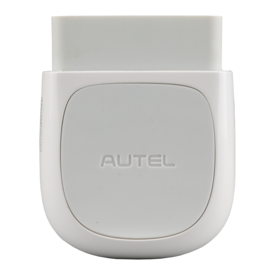
Page 9: General Introduction
Vehicle Data Connector (16-pin) – connects the MaxiAP AP100 to the vehicle’s 16-pin DLC directly. Power LED – indicates system status. The power LED displays green, blue, red depending on power level and operating state. A. Green Lights solid green when the MaxiAP AP100 is plugged in and not... -
Page 10: Technical Specifications
Lights solid red when the MaxiAP AP100 is updating the firmware or the update failed. NOTE The power LED goes off when the MaxiAP AP100 disconnects with the device for over 10 minutes and enters the standby mode with low power consumption. The power LED comes back on with reconnection. -
Page 11: Wireless Communication
MaxiAP AP100 connector. Power Source The MaxiAP AP100 operates on 12-volt vehicle power, which it receives through the vehicle data connection port. The unit powers on whenever it is connected to an OBDII/ EOBD compliant data link connector (DLC). -
Page 12: Getting Started
Search for MaxiAP from App Store or Google Play to download and install to your device. Or scan the QR code to download the MaxiAP AP100 app. Register & login Open the MaxiAP app and select Connect later. ... - Page 13 Tap Me>VCI Management or the VCI button on the top left of the Home screen to enter the VCI Management screen. Tap the Bluetooth name of the MaxiAP AP100 and pair up with the device. The Bluetooth name starts with AP followed by the MaxiAP AP100’s serial number.
-
Page 14: Application Buttons
③ Navigation Buttons Application Buttons The table below briefly describes each of the applications in the MaxiAP system. Table 3-1 Applications Button Name Description Reads the diagnostic trouble codes. See Read Read DTCs DTCs on page 10. Clears the diagnostic trouble codes. See Clear Clear DTCs DTCs... - Page 15 Table 3-2 Navigation Buttons Button Name Description Home Returns to the Home screen. Live Displays system live data. Personal center for register, log in, settings, etc.
-
Page 16: Read Dtcs
Read DTCs This option can read and clear pending, stored, permanent codes for 1996 and newer European, Asian, and U.S. OBDII/EOBD compatible vehicles. It can also read and clear enhanced codes for engine and transmission systems of GM, Chrysler, and Ford vehicles. The vehicle coverage and available modules will be increased with regular software update. -
Page 17: Clear Dtcs
Clear DTCs There are two ways to clear trouble codes. Tap Read DTCs, when the scan completes, tap Clear on the top and pick the codes you want to clear. You can clear Engine codes, ABS codes or both at the same time. Wait for codes to be cleared. Clear codes directly from the Home screen without having to read codes first. -
Page 18: Repair Reports
Repair Reports The MaxiAP app automatically saves a repair report for each diagnostic session that can tell you what is wrong with your vehicle. Based on the trouble codes in the specific vehicle, a repair report contains the definition of the DTCs (stored codes, pending codes, permanent codes and manufacture-specific codes) and possible causes. -
Page 19: Smog Check
Smog Check This function is used to check the readiness of the monitoring system. It is an excellent function to use prior to having a vehicle inspected for state emissions compliance. The AP100 can tell you if you are ready for your test, if you will fail your test, or if you may fail your test. - Page 20 Table 7-1 Indicator Button Button Description Indicates the monitoring item is complete. Indicates the monitoring item is not complete. Indicates the MIL is on. Indicates the MIL is off. Indicates the monitoring item is not supported.
-
Page 21: Mode 6
Mode 6 Mode 6 refers to the advanced test results for On-Board Diagnostic System Monitors. Example monitors include Oxygen Sensors and Misfire Counters. Figure 8-1 Sample Mode 6 Screen Mode 6 will tell you if the monitors are passing their tests and if the values are within acceptable range. -
Page 22: Freeze Frame
Freeze Frame Freeze Frame provides a snapshot of vehicle data at the instant the Check Engine Light (CEL) came on. Tap Freeze Frame. When the scan completes, freeze frame data is available to be viewed. Figure 9-1 Sample Freeze Frame Screen... -
Page 23: Vehicle Info
Vehicle Info With the embedded AutoVIN technology, this option displays the vehicle identification number (VIN), the calibration identification, the calibration verification number (CVN), vehicle brand, model, year, and other information of the test vehicle. Tap Vehicle Info to view the detailed vehicle information that is based on vehicle VIN. -
Page 24: Mil Status
MIL Status The Check Engine Light is also known as the Malfunction Indicator Lamp, or MIL, and has more information to share besides being ON or OFF. Tap MIL Status to display the MIL related information. The information mainly include, MIL Status (ON or OFF), Run Time Since Engine Start, Distance with MIL ON, and Distance Since Trouble Code Cleared. -
Page 25: Live Data
Live Data Tap Live to view the list of available live data. Tap the button to view the details of a specific live data. The details screen displays the descriptions and you can change the display mode, unit, and custom range. When this function is selected, the screen displays the data list for the selected module. -
Page 26: Register
Register Tap the Register button on the Settings screen. Enter the email address, verification code and password accordingly in the register screen. The verification code will be sent to your email address after you tap the Verification code button. Tap Register at the end to complete the registration. Figure 13-1 Sample Register Screen Log in After registering the tool, log in with your registered email and password. -
Page 27: Online Purchase
Manages the Bluetooth connection. To connect the device with the MaxiAP AP100, turn on the device’s Bluetooth beforehand. Tap the Bluetooth name of the MaxiAP AP100 to pair up with the device. When the device is successfully paired up and communicating with the MaxiAP AP100, the LED on the MaxiAP AP100 lights solid blue. -
Page 28: Settings
Figure 13-3 Sample VCI Management Screen Settings Select the Settings application to open a setup screen to adjust the default setting and view information about the MaxiAP system. There are five system settings. Device Activate Firmware update Unit ... -
Page 29: Device Activate
Figure 13-4 Sample Settings Screen Device Activate The MaxiAP AP100 needs to be activated after first log in. Connect the device with the MaxiAP AP100 connector and then tap Me>Settings>Device Activate in the app to activate the device. Please refer to Powering Up page 6 for VCI connection details. -
Page 30: Firmware Update
Firmware Update This options allows you to update the firmware of the MaxiAP AP100 connector. Connect the device with the Internet and then tap Me>Settings>Firmwadumre Update to update if new firmware version is available. Figure 13-6 Sample Firmware Update Screen... -
Page 31: About
About The About option displays the following information, current version of the app, Eobd version, User Manual, Privacy Policy & Terms of Use. You can tap User Manual and Privacy Policy & Terms of Use to view detailed information. Figure 13-7 Sample About Screen... -
Page 32: Product Troubleshooting
This part describes problems that you may encounter while using the MaxiAP AP100. Vehicle Linking Error A communication error occurs if the MaxiAP AP100 fails to communicate with the vehicle’s control module when performing diagnostic procedures. Please do the following check-ups: ... -
Page 33: Compliance Information
Compliance Information FCC COMPLIANCE FCC ID: WQ82017MAXIAP This device complies with Part 15 of the FCC Rules and with RSS-210 of Industry Canada. Operation is subject to the following two conditions: This device may not cause harmful interference. This device must accept any interference received, including interference that may cause undesired operation. - Page 34 This equipment complies with FCC radiation exposure limits set forth for an uncontrolled environment. This equipment should be installed and operated with minimum distance 20cm between the radiator & your body. RoHS COMPLIANCE This device is declared to be in compliance with the European RoHS Directive 2011/65/EU.
-
Page 35: Warranty And Service
Limited One Year Warranty Autel Intelligent Technology Corp., Ltd. (the Company) warrants to the original retail purchaser of this Autel device that should this product or any part thereof during normal usage and under normal conditions be proven defective in material or workmanship that results in product failure within 1... -
Page 36: Service And Support
Service and Support If you have any questions regarding the product, please contact one of our offices in your region. AUTEL NORTH AMERICA Phone: 855-AUTEL-US (855-288-3587) Monday-Friday 9am-6pm Website: www.autel.com Email: ... - Page 37 Address: Office 103, Building 3845, International Business Park, Veracruz, Panamá Pací fico, Panamá AUTEL AUSTRALIA Phone: 03 9480 2978 / +61 476293327 Website: www.autel.com.au Email: sales@autel.com.au Address: 155 Islington Street, Melbourne, Collingwood, VIC For technical assistance in other markets, please contact your local...
Need help?
Do you have a question about the MaxiAP AP100 and is the answer not in the manual?
Questions and answers