
Related Manuals for aldes CO2 Sensor


Summary of Contents for aldes CO2 Sensor
- Page 1 Capteur CO Sens Notice d’installation Installation instructions Sensor CO Sens Installationsanleitung Sensor Sensor CO Sens Montagehandleiding Sensor CO Sens Manual de instalación Sensore CO Sens Manuale di installazione...
- Page 2 1. ATTENTION • CAUTION • VORSICHT • LET OP • ATENCIÓN • ATTENZIONE • L’appareil ne doit pas être exposé à des contraintes mécaniques ou thermiques extrêmes. • L’appareil ne convient pas aux applications de sécurité, aux arrêts d’urgence ou à d’autres applications critiques dans lesquelles un dysfonctionnement ou une panne de l’appareil pourrait provoquer des blessures.
- Page 3 • Das Gerät darf keinen extremen mechanischen oder thermischen Belastungen ausgesetzt werden.. • Das Gerät ist nicht für Sicherheits-, Not-Aus- oder andere kritische Anwendungen geeignet, bei denen Menschen durch seine Fehlfunktion oder seinen Ausfall verletzt werden könnten. • Die Elektronikplatine als ESD-empfindliches Gerät ist entsprechend zu behandeln und sollte während der Installation nicht berührt werden. •...
- Page 4 • El dispositivo no debe exponerse a tensiones mecánicas o térmicas extremas. • El dispositivo no es adecuado para aplicaciones de seguridad, paradas de emergencia u otras aplicaciones críticas en las que un disfuncionamiento o un fallo del equipo podrían provocar lesiones. •...
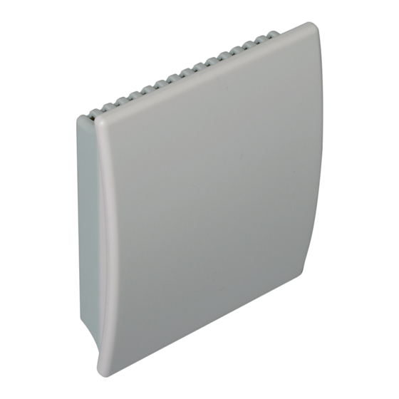
- Page 5 2. ENCOMBREMENT • ENCOMBREMENT • PLATZBEDARF • AFMETINGEN • DIMENSIONES • INGOMBRO • L’électronique se situe derrière le cache avant, qui s’installe et se retire facilement une fois le cache arrière fixé au mur (D = trous de fixation) et l’appareil câblé.
- Page 6 • Die Elektronik befindet sich in der Frontabdeckung, die einfach auf- und abgeknipst werden kann, nachdem die hintere Abdeckung an der Wand befestigt (D=Montagebohrungen) und verdrahtet wurde. • ÖFFNEN DES GEHÄUSES: Den Riegel A drücken, um ihn zu lösen, bis das Gehäuse geöffnet werden kann. Einen Schraubendreher oder einen Stift verwenden. •...
- Page 7 • La electrónica se sitúa detrás de la tapa frontal, que se acopla/desacopla fácilmente una vez que la tapa trasera se haya fijado en la pared (D=orificios de montaje) y cableado. • APERTURA DEL CAJETÍN: Presione para soltar el enganche A hasta que se pueda abrir el cajetín. Utilice un destornillador o un bolígrafo. •...
-
Page 8: Voltage Output
3. SCHÉMA DE RACCORDEMENT • CONNECTION DIAGRAM • SCHALTPLAN • AANSLUITSCHEMA • ESQUEMA DE CONEXIÓN • SCHEMA DI COLLEGAMENTO Le fabricant ne peut être tenu pour responsable de toute blessure ou de tout dommage matériel résultant d’une manipulation, d’une installation, d’un câblage, d’une alimentation ou d’un entretien incorrects de l’appareil. - Page 9 Der Hersteller haftet nicht für Personen- oder Sachschäden, die durch unsachgemäße Handhabung, Installation, Verdrahtung, Stromversorgung und Wartung des Geräts entstehen. SPANNUNGSAUSGANG 15...35V DC 24 VAC ±20 % Konfigurations- anschluss Output: 0-5 V Ausgang: 0-5 V 0-10 V 0-10 V STROMAUSGANG 15...35V DC 24 VAC ±20 % Konfigurations-...
- Page 10 El fabricante no puede ser considerado responsable de ninguna lesión o daño material producidos por una manipulación, instalación, cableado, alimentación o mantenimiento incorrectos del equipo. SALIDA DE TENSIÓN De 15 a 35 V CC 24 V CA ±20 % Conector de configuración Output: 0-5 V Salida:...
-
Page 12: Other Countries
FRANCE - Vous êtes un client professionnel : 09 69 32 39 98 (n° Cristal, prix d’un appel local) • ata.stve@aldes.com - Vous êtes un client particulier : 0 810 20 22 24 (n° Azur, 0,06€ la minute) • service-conso@aldes.com Besoin d’une assistance technique après-vente ?
Need help?
Do you have a question about the CO2 Sensor and is the answer not in the manual?
Questions and answers