Table of Contents
Advertisement
Quick Links
Advertisement
Table of Contents

Subscribe to Our Youtube Channel
Summary of Contents for FLTR CCM 01
- Page 1 CCM 01 - Set Contamination Control Monitor Instruction manual Version 2.7 Serial no. CCM 01: ....Serial no. PFS 01: ....Version valid from: 22.08.2016 For more information: WEB: FLTR.com.au PHONE: (+61) 1300 62 4020 EMAIL: info@FLTR.com.au SKYPE: Purple.Engineering...
-
Page 2: Table Of Contents
3.2.4. Protocol for the contiuous data transfer ............21 3.3. Data transfer of the saved measurements ............. 22 Export and evaluation of the stored data via “CCM 01 data manager Vers. 2.0”22 3.3.1. 3.3.2. One-time program installation ................ 22 3.3.3. - Page 3 CCM 01 – Display unit ................... 40 7.1.2. CCM 01 – housing ..................41 7.1.3. 7.1.3.1. CCM 01 - backside of housing ..............41 7.2. Pin assignment ....................42 7.2.1. Laser sensor ....................42 CCM 01 – display unit ..................42 7.2.2.
-
Page 4: Safety Information
Maximum acceptable volume flow: 50 l/min / 13 gal/min Generally, the CCM 01 – Set has to be operated with 24 V DC (ripple: < 300 mV For more information: WEB: FLTR.com.au PHONE: (+61) 1300 62 4020 EMAIL: info@FLTR.com.au SKYPE: Purple.Engineering... -
Page 5: Operation And Installation
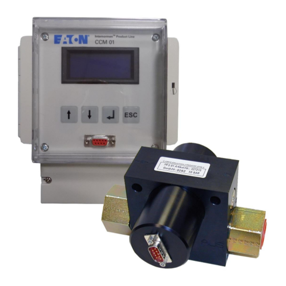
Operation and installation 2.1. Setup The CCM 01 – Set consists of the PFS 01 (Particle Flow rate Sensor), a cable to connect the sensor (l = 5 m) and the CCM 01 – display unit. A PFS 01 belongs always to a specific CCM 01. The calibration values of the PFS 01 are stored always in the respective CCM 01! 2.1.1. -
Page 6: General Information
- Transmission of the stored measured data on an external cpmputer in a Windows Excel file. The CCM 01 – Set should only be switched on when the PFS 01 is flown through with oil, because there is installed a thermic volume flow sensor. Very long runnning times without flow rate can cause damages! 2.3. -
Page 7: Sensor Installation
20 l/min. 2.6. Installation of the display unit CCM 01 Mount the CCM 01 display unit to the system. (see chapter 7.1.3.1) 2.7. Electrical connection of the PFS 01 and the CCM 01 Connect the display unit with the sensor using the cable. Extend the sensor cable after consultation with the manufacturer only. - Page 8 Cable screws: PG 9 PG 11 PG 13,5 4 – 8 mm 5 – 10 mm 6 – 12 mm Cable diameter: Place the 24 V DC power cable through the screwed cable gland PG 9 or 13.5 (depending on cable size) and connect it (see chapter 7.2 or the list on the cover). Put the threshold transmission cable in the screwed cable gland PG 9 or PG 13.5 (depending on cable size) according to the pin assignment (see chapter 7.2 or the list on the cover).
- Page 9 The CCM 01 set is ready for operation, if the laser sensor, the power cable and the threshold transmission cable are connected to the CCM 01 display unit.
-
Page 10: Operating The Ccm 01 Software
2.8. Operating the CCM 01 software After the sensor has been entered into the hydraulic system, considering all application limits, start the CCM 01. Wait through the welcome screen until the main menu is being displayed. It can be operated using the control keys. -
Page 11: Menu Structure
Transfer Data Set Limits CAN Baudrate Viscosity Range Report Format Delete Data Set Time CAN Node ID Stored Data Calibration Start Start (display only) Storage Intervall For more information: WEB: FLTR.com.au PHONE: (+61) 1300 62 4020 EMAIL: info@FLTR.com.au SKYPE: Purple.Engineering... -
Page 12: Main Menu
2.8.3. Main menu Choose a submenu with the [ ] buttons. The chosen item is marked with a * on the left side of the menu. Enter the chosen menu item by hitting the [ ] button. 2.8.3.1. -
Page 13: Start
During the measuring the particles per counting channel and the volume flow constantly put out via the RS232 interface. (see chapter 3.2) Serially, the CCM 01 comes with the data manager software. This software edits and manages measurements stored by the CCM 01. ... -
Page 14: Data Manager
2.8.3.2. Data Manager This submenu serves for transferring and deleting of the saved measurements. Choose submenu with the [ ] buttons. The chosen item is marked with a * on the left side of the menu. Enter the chosen menu item by hitting the [ ... -
Page 15: Data Transfer By Using The External Printer
The chosen item is marked with a * on the left side of the menu. Enter the chosen menu item by hitting the [ ] button. Use [ ESC ] to go back to the previous menu. For more information: WEB: FLTR.com.au PHONE: (+61) 1300 62 4020 EMAIL: info@FLTR.com.au SKYPE: Purple.Engineering... -
Page 16: Limits
2.8.3.3.1. Limits When achieving or exceeding the set limit values in the measuring cycle the corresponding threshold contacts switch or rather close. With the setting of zero values the functionality of the threshold contacts is switched off no switching or rather closing of the threshold contacts. ... -
Page 17: Set Time
2.8.3.3.2. Set Time This function allows setting the real time clock that is integrated in the device. Due to the back-up battery, the clock will keep running even if the power supply is shut off. Day, month, year, hour and minute can be adjusted individually and they are being transmitted to the real time clock when the menu is being closed. -
Page 18: Can
Detail informations and instructions see chapter 5 CAN interface Data transfer The data transfer from the CCM 01 to external computers is principle made by using the RS232 - interface. The data can be transferred with an interface cable as well as wirelessly with a Bluetooth modul. -
Page 19: Connection To An External Computer As An Evaluation Device
3.2. Continuous data transfer of the actual measurements In this mode it is possible to transfer the actual measurement results from the CCM 01 to an external computer via RS232 or the Bluetooth modul EBT 01. (see chapter 3.1) The... -
Page 20: Setup Of Hyperterminal
3.2.2. Setup of HyperTerminal One-time setup of HyperTerminal under: START / PROGRAMS / ACCESSORIES / COMMUNICATIONS / HYPER TERMINAL Choose a symbol and enter a name (e.g. CCM 01). Confirm with OK. Choose the COM - port... -
Page 21: Procedure
Procedure Connect the CCM 01 to an external computer (RS232 or Bluetooth) Select „MEASURE“ in the main menu of the CCM 01 and confirm. Start the measuring mode with „START“. Stored data is provided periodically to the RS232 – interface or the Bluetooth EBT 01. -
Page 22: Data Transfer Of The Saved Measurements
$M;371.08;29.44;2.92;0.74;50.00;02;01;2006;08;15;01* 3.3. Data transfer of the saved measurements In the mode „ Data transfer“stored measurements can be transferred from the CCM 01 to an external computer. For this purpose, connect the CCM 01 using the serial interface RS232 with the external Computer. -
Page 23: Procedure
The saved data is provided cyclically. The supply cycle can be quit with [ESC]. (4) Check the connection between the CCM 01 and the external computer by using the button „Terminal“ in the main menu of the data manager program. - Page 24 If an empty terminal window appears, select the right COM port and check the connection again. (5) Clicking the button „Data Manager“ allows the export of the data and further processing of the measured data. (6) Data transfer by using the button „START TRANSFER“. ...
- Page 25 Afterwards the data transfer starts. (7) The transferrred data can be: (a) charted (b) exported in an EXCEL – data sheet...
- Page 26 Export into an Excel – data sheet via the button „EXCEL“ For further processing of the data, all standard functions are available in EXCEL. c) Printing a report via the button „PRINT“ For more information: WEB: FLTR.com.au PHONE: (+61) 1300 62 4020 EMAIL: info@FLTR.com.au SKYPE: Purple.Engineering...
- Page 27 CCM01 Report Eaton Technologies GmbH (8) Closing the data manager software via the button „CLOSE“.
-
Page 28: Evaluating Measurements
Evaluating measurements The contamination classes, calculated on the basis of the determined particle numbers each counter channel, will be displayed according to the selection type (ISO 4406 or NAS 1638). (see chapter 2.8.3.1.2) The actual particle numbers saved according to the selected classification type per counting channel can be forwarded to an external computer by means of RS232 interface or bluetoothmodule EBT01 and by applying the supplied data manager software 2.0 or another communication programme;... -
Page 29: Can Interface
CANopen-functions. In this chapter there is a small introduction to the fieldbus system CAN and the higher layer protocol CANopen and a description of controlling the CCM 01 via CAN. 5.1. Introduction to CAN and CANopen 5.1.1. CAN-Bus ... -
Page 30: Canopen - Functionality
The objects or parameters are addressed with a 16-bit index and an 8-bit subindex. The build-up of the object dictionary and the access to it is described in the following chapters. CANopen defines different objects for communication. These are: Service Data Object (SDO): For parameter settings Process Data Object (PDO):... -
Page 31: Baudrate
Choose the submenu CAN with the [ ] buttons. Enter the chosen menu item by hitting the [ ] button. Now there is the menue for adjusting the baudrate, the node ID and for starting the controlling with CAN. -
Page 32: Start
Use [ ESC ] to go back to the previous menu – changes will not be adopted. The default node ID is 1. 5.3.3. Start For starting the controlling with CAN use the [ ] buttons to select the item START. ... -
Page 33: Communication Specific Part
Every bit stands for a specific error. If a bit is set this error is active. The buildup of this register is as follows: For more information: WEB: FLTR.com.au PHONE: (+61) 1300 62 4020 EMAIL: info@FLTR.com.au SKYPE: Purple.Engineering... -
Page 34: Manufacturer Specific Part
Manufacturer Status Register Bit8 Bit7 Bit6 Bit5 Bit4 Bit3 Bit2 Bit1 Bit0 Limit Limit Limit Limit Limit Limit Limit Limit Flow 5 – 15 15 – 25 25 – 50 4 µm 6 µm 14 µm 21 µm Sensor µm µm µm µm... -
Page 35: Threshold Settings
5.4.2.1. Threshold settings The indexes 3000h to 3007h of the object dictionary are for threshold settings. The limit values according ISO 4406 can be changed at the index 3000h – 3003h. The limit values according NAS 1638 can be changed at the index 3004h – 3007h. ... -
Page 36: Process Values
It is a client-server communication. A client request is always confirmed by a reply from the server. The CCM 01 represents an SDO-Server. For an SDO transfer following COB-IDs are used: COB-ID Description SDO Client CCM01 0x600 + Node ID CCM01 ... -
Page 37: Transmit Pdo
4 Byte data Response The CCM 01 supports only the transmission of data with a maximum length of 4 Byte! 5.6. Transmit PDO The CCM 01 has one Transmit PDO (TPDO). This contains the measurement results in contamination classes according ISO 4406 or NAS 1638. -
Page 38: Timestamp
CANopen configuration tool. 5.12. Examples for CAN-communication In this chapter there are some examples for controlling the CCM 01 via CAN. All numbers are in hexadecimal representation. Node ID 5, request limit 4 µm: Identifier 8 Byte Data... - Page 39 When only the PFS 01 sensor was sent to calibration, the calibration values must be entered into the CCM 01. If the laser sensor is recalibrated or exchanged, also the programmed calibration values in the CCM 01 have to be changed. The input of the new calibration values is described in chapter 2.8.3.3.3...
-
Page 40: Appendix
Weight: 1,5 kg / 3,3 lb (m) Operating fluids: Mineral oil based hydraulic- and lubricating fluids (see separate list for compatibility) CCM 01 – Display unit 7.1.2. Measuring method: Automatic particle counting Particle sizes (switchable): > 4 µm , > 6 µm , >14 µm... -
Page 41: Ccm 01 - Housing
Material: ABS (Acrylonitrile butadiene styrene) and polycarbonate EPDM (Ethylene/ Propylene – Dien Sealing material: polymer) Protection class: IP 65 Dimensions: 160 x 185 x 110 mm x mm x mm Weight: 1,28 kg 7.1.3.1. CCM 01 - backside of housing... -
Page 42: Pin Assignment
→ ) + 5 V DC 7: brown CCM 01 – display unit 7.2.2. RS 232 interface and CAN – option 7.2.2.1. CAN – option SV 2 RESET SV 1 RS-232 For more information: WEB: FLTR.com.au PHONE: (+61) 1300 62 4020 EMAIL: info@FLTR.com.au SKYPE: Purple.Engineering... -
Page 43: Sensor Connections - X11
Sensor connections – X11 7.2.2.2..blue - → ) 4...20 mA flow rate sensor ..green - → ) laser particle sensor ../ 5 – 15 µm) REL 4 contact 1 ( 4 µm / 15 – 25 µm) REL 3 contact 1 ( 6 µm / 25 –... -
Page 44: Pressure Difference Characateristics
7.3. Pressure difference characateristics Pressure difference characteristics of the PFS 01 mit HLP 46 20°C 25°C 30°C 35°C 40°C 45°C l/min... -
Page 45: Cleanliness Classes According To Iso 4406:99
7.4. Cleanliness classes according to ISO 4406:99 According to ISO 4406 (year 1999) the number of particles sized > 4 µm , > 6 µm and > 14 µm is being used to determine the cleanliness class. The determination of the cleanliness class doesn’t depend on the particle size. -
Page 46: Cleanliness Classes According To Nas 1638
7.5. Cleanliness classes according to NAS 1638 Analysis volume: 100 ml Particle number x 10³ Class 5 - 15 µm 15 - 25 µm 25 - 50 µm 50 - 100 µm > 100 µm 0,125 0,022 0,004 0,001 0,250 0,044 0,008 0,002... -
Page 47: Application Areas - Compatibility
Malfunctions, which could be eliminated by the operator, are limited to cleaning the sensor and checking cables for brakes. Any other case requires sending in the sensor or the display unit CCM 01 to Eaton Technologies GmbH in order to recover the functions. - Page 48 For more information: WEB: FLTR.com.au PHONE: (+61) 1300 62 4020 EMAIL: info@FLTR.com.au SKYPE: Purple.Engineering...
Need help?
Do you have a question about the CCM 01 and is the answer not in the manual?
Questions and answers