Table of Contents
Advertisement
Quick Links
S.a.s. di Guazzetti Giovanni e C.
COSTRUZIONI MECCANICHE ELETTRICHE
Instruction and Maintenance Rules for:
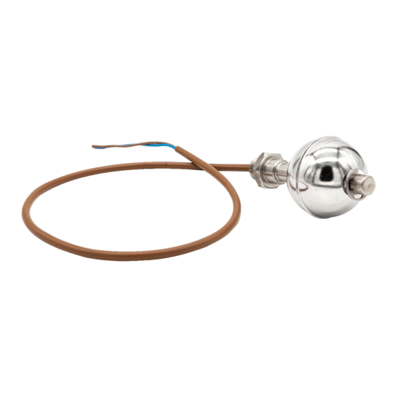
Float level indicator CLR20
CLR20-1, CLR20-2, CLR20-3, CLR20-C/1, CLR20-C/2, CLR20-C/3
STANDARD FEATURES
The CLR20 is a sensor for the detection of level thresholds on any type of liquid.
The operating principle is based on a permanent magnet (encapsulated inside the
oat) and frictionless reed contacts.
Signal output: SPST (alternatively, NO or NC contact), up to 3 intervention points);
-
MAX switch power*: 80 VA
-
MAX switch voltage*: 250V AC/DC
-
MAX switch current*: 1.3 A
-
* all indications are for resistive loads only
2
Cable size: 2x1mm (AWG17) / 150°C / L=600 mm
-
Connection to process: G 3/8 BSPP
-
Process temperature: -10 ... +70 °C
-
MAX pressure: 15 bar
-
Materials: ow EN1.4571 (AISI 316Ti), body EN1.4401 (AISI 316)
-
Mounting type: internal, vertically ±30° / horizontally for the curved version
-
Minimum uid density: 0,7 Kg/dm
-
Length: from 85 to 2000 mm
-
SAFETY RULES
All the operations described in this documentation must be carried out only by qualied personnel, authorized by the plant manager,
applying the appropriate safety precautions to reduce risk of re, electric shock or injury.
Operational safety of the appliance is only guaranteed if used in compliance with regulations, in accordance with the instructions for use
and any additional instructions. Arbitrary transformations or modications are strictly prohibited. In case of improper use, the appliance
can be a source of dangers associated with the specic application, or damage to the plant, following incorrect assembly or adjustment.
Check that the power supply system complies with the regulations, with built-in automatic protection switch.
Any inspection, cleaning, maintenance, change or replacement of parts must be carried out with the indicator unpowered and plug
disconnected from the power supply.
INSTALLATION
Before installation, carry out a visual check of the equipment to make sure
that it has not suffered any damage during transport or storage.
If the control reveals anomalies, the product must be sent to the manufacturer
to restore efciency.
The CLR20 indicator must be installed inside the tank, in a vertical position (A)
with a maximum error of ± 30 degrees, or in a horizontal position (C) for the
curved version only. Make sure that there are no external magnetic elds that
could alter the operation of the reed.
ELECTRICAL CONNECTION
Disconnect the power supply before proceeding with the electrical
connection of the device. For voltages above 50V, make sure that the
indicator is grounded correctly. In the case of tanks of insulating material,
always connect the indicator body to the ground with a suitable eyelet (* not
supplied) screwed under the external nut.
Also available in version with M12 connector (for voltages up to MAX 150V).
OPERATION
The rising level of a liquid causes the oat to rise, which runs vertically guided
by the body of the indicator. When the permanent magnet, encapsulated in the
oat, comes in the proximity of the reed contact, it causes it to close by
switching the state of the signal circuit.
The indicator does not require external power sources. To reverse the
operating mode, remove the stop ring at the end and reverse the oat.
The indication stamped on the sphere towards the threaded end indicates the
operating mode: NC = closed circuit in the absence of liquid; NO = open
circuit in the absence of liquid.
MAINTENANCE
Periodically check that there are no solid deposits (e.g. limescale) on the central rod of the indicator body that could obstruct the
movement of the oat. The electrical components inside the indicator do not require any maintenance.
R
R
Via dell'Industria 12 - 12/A - 42025 CAVRIAGO - RE - Italy
Tel.: 0522/942641 - 0522/941172
www.camlogic.it
3
e-mail: camlogic@camlogic.it
A
B
L1
L1
MAX
NO
NC
L2
MIN
2
1
2
NO
NC
1
NO
(normally open)
NO
NC
C
L1
NO
NO
NC
NC
2
1
2
NC
NO
1
NC
(normally closed)
Advertisement
Table of Contents

Subscribe to Our Youtube Channel
Related Manuals for Camlogic CLR20


Summary of Contents for Camlogic CLR20
- Page 1 CLR20-1, CLR20-2, CLR20-3, CLR20-C/1, CLR20-C/2, CLR20-C/3 STANDARD FEATURES The CLR20 is a sensor for the detection of level thresholds on any type of liquid. The operating principle is based on a permanent magnet (encapsulated inside the oat) and frictionless reed contacts.
- Page 2 WARRANTY CAMLogic, in addition to the terms of the supply contract, guarantees its products for a period of twenty-four (24) months from the date of shipment. This warranty is expressed only in the repair or replacement free of charge of parts that, after careful examination by the Manufacturer, turn out to be defective.
Need help?
Do you have a question about the CLR20 and is the answer not in the manual?
Questions and answers