Advertisement
Quick Links
Advertisement

Summary of Contents for Sices DST4601
- Page 1 Filename: EAAM005709EN.docx Rev. 09 Date: 06/05/2013 ID Document: EAAM0057 Product: DST4601...
- Page 2 1 General Information ..................... 3 1.1 Definition ........................3 1.2 Symbols ........................3 2 Front Panel ........................4 2.1 Commands ....................... 4 2.1.1 Key-lock selector ....................4 2.1.2 Pushbuttons ....................5 2.2 Display ........................6 2.2.1 MEASURES Display ..................6 2.2.2 MULTIFUNCTION Display ................
- Page 3 It works with both three- and single-phase systems. Please refer to SICES document EAAM008800 (or following versions) for programming and default values.
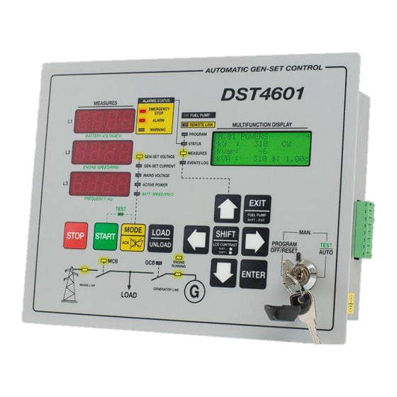
- Page 4 Command operations are carried out by means a key-lock switch and 11 pushbuttons. Key position Function OFF/RESET PROGRAM Gen-set is disabled. All the alarms are reset. It is possible to gain access to programming function. MAN. Gen-set is in manual mode. AUTO / TEST Gen-set is in automatic mode.
- Page 5 2.1.2 Button Function SHIFT Dead key. Pressed together with another pushbutton, changes the pushbutton function. They allow selecting previous or followings pages of multifunction display if in Right arrow STATUS, MEASURES or EVENT LOG mode. Left arrow In Program mode, they are used to move the cursor while keying character strings.
- Page 6 2.2.1 It consists of three LED displays of four digits each. Display function is selectable by means MODE pushbutton. For generator measures, L1, L2 and L3 inscriptions show relations between phases and functions and the display-selected function. The selectable modes are the followings: GEN-SET VOLTAGE phase to phase GEN-SET VOLTAGE phase to neutral GEN_SET CURRENT...
- Page 7 This mode allows showing and modifying all the programming parameters. Scroll menus by means up and down arrows to select an entry and press ENTER to confirm selection. Select then the variable or another menu. At the end of menu tree, there are variable lists: variable in lists are shown by dedicate page for each variable.
- Page 8 Signals Function Signals the EMERGENCY STOP command activation. If flashing, the status isn’t already acknowledged (it is to press the MODE/ACK EMERGENCY STOP pushbutton). Signal a BLOCK or a DISABLE. If flashing, the status isn’t already ALARM acknowledged (it is to press the MODE/ACK pushbutton). Signal a WARNING.
- Page 9 Connectors JA, JB and JC are the terminals of the optocoupled inputs of the board. These inputs are active if connected to ground. Some inputs have programmable functions that can be changed by a programming menu. Terminal Function JA 01 Auxiliary alarm (BLOCK) input.
- Page 10 Terminal Function JB 13 INPUT 13 AUX INPUT 1. Free programmable input. JB 14 INPUT 14 AUX INPUT 2. Free programmable input. JB 15 INPUT 15 AUX INPUT 3. Free programmable input. INPUT 16 MIN FUEL LEVEL Programmable input preset to the MINIMUM FUEL JC 16 LEVEL function.
- Page 11 Terminal Function JL 50/51 TA input, L1 phase JL 52/53 TA input, L2 phase JL 54/55 TA input, L3 phase JN 63 Generator Voltage phase L1 JN 65 Generator Voltage phase L2 JN 67 Generator Voltage phase L3 JN 68 Generator Voltage neutral line N JO 70 Mains/Grid Voltage phase L1...
- Page 12 If active, they connect the input to ground otherwise they are open circuit. Terminal Output type Function Open ENGINE RUNNING. Programmable output preset to signal an JG 40 collector, engine running status. 350mA. Open WARNINGS. Programmable output preset to signal the JG 41 collector, presence of one or more warnings.
- Page 13 Connect a direct current source in range starting from 7.5V to 32V. Negative terminal (GND) should be externally connected to reference and safety earth. For application having separate GND and HEARTH, please ask to SICES for proper working condition. 3.5.2 JI is used to interface external RS232 device.
- Page 14 Please refer to SICES document EAAM008800 (or following versions) for programming and default values. Program access can be restricted by means a password. There are 3 different access level and password: 1.
- Page 15 It is possible to directly access the last used page. If the EXIT key is pressed for about 3 seconds, programming function is left and the displayed page is stored. When programming is again entered, this page is shown at first (then, if required, pressing EXIT it is possible to go up trough menus).
- Page 16 4. Press MODE and EXIT pushbutton together for at least 5 seconds. 5. After 5 seconds all the page counters will be cleared. DST4601 board can shows text strings in different languages. To select a language, keep pressed STOP and START button together while supplying the board (selector key in OFF/RESET).
- Page 17 MAN-ON (pump activated) MAN-OFF (pump deactivated) The second mode can be inhibited by the DST4601, relating to the fuel level (the pump cannot be started with full tank). DUE TO THE HIGH VOLTAGE CONNECTED TO THE MEASURE INPUTS, THE DEVICE ENCLOSURE MUST BE CONNECTED TO SAFETY GROUND.
- Page 18 WASHER Ø4 SPRING WASHER Ø4 EXAGONAL NUT 4MA HOLE Ø 5MM 18 User’s Manual...
- Page 19 This document is owned by SICES s.r.l.. All rights reserved. SICES s.r.l. reserves the right to modify this document without prior notice. SICES has made any effort to ensure that the information herein provide are correct; in any case SICES does not assume any liability for the use these information.

Need help?
Do you have a question about the DST4601 and is the answer not in the manual?
Questions and answers