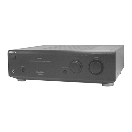
Sony TA-F448EB Service Manual
Integrated stereo amplifier
Hide thumbs
Also See for TA-F448EB:
- Service manual (19 pages) ,
- Operating instructions manual (18 pages)
Advertisement
Quick Links
SERVICE MANUAL
Amplifier section
DIN power output
85 W + 85 W (4 ohms at 1 kHz)
55 W + 55 W (8 ohms at 1 kHz)
Total harmonic distortion
Less than 0.008% (at 10 W output)
Frequency response
PHONO (20 Hz – 20 kHz): RIAA equalization curve ±0.5 dB
TUNER, CD, AUX, TAPE1/DAT, TAPE2/MD: 7 Hz – 100 kHz
S/N (network A)
PHONO: 94 dB
TUNER, CD, AUX, TAPE1/DAT, TAPE2/MD: 105 dB
Output voltage/impedance
RECOUT: 150 mV, 1 kilohm
PHONES: 10 mW (at 8 ohms)
Speakers impedance
4 – 16 ohms, 8 – 16 ohms (SPEAKERS A + B)
Damping factor
100 (8 ohms, 1 kHz)
MICROFILM
TA-F448EB
SPECIFICATIONS
General
System
Power amplifier: Pure-complementary SEPP OCL power amplifier with
all stages directly coupled
Preamplifier: Low-noise, equalizer amplifier
Power requirements
230 V AC, 50/60 Hz
+11
–3
Power consumption
dB
180 W
Dimensions (approx.) (w/h/d)
430 × 135 × 365 mm
incl. projecting parts and controls
Mass (approx.)
6.8 kg
Design and specifications are subject to change without notice.
INTEGRATED STEREO AMPLIFIER
AEP Model
UK Model
Advertisement

Summary of Contents for Sony TA-F448EB
- Page 1 TA-F448EB SERVICE MANUAL AEP Model UK Model SPECIFICATIONS Amplifier section General DIN power output System 85 W + 85 W (4 ohms at 1 kHz) Power amplifier: Pure-complementary SEPP OCL power amplifier with 55 W + 55 W (8 ohms at 1 kHz)
-
Page 2: Table Of Contents
LINE WITH MARK ! ON THE SCHEMATIC DIAGRAMS AND IN THE PARTS LIST ARE CRITICAL TO SAFE OPERATION. REPLACE THESE COMPONENTS WITH SONY PARTS WHOSE PART NUMBERS APPEAR AS SHOWN IN THIS MANUAL OR IN SUPPLEMENTS PUB- LISHED BY SONY. -
Page 3: General
SECTION 1 This section is extracted from instruction manual. GENERAL – 3 –... - Page 4 – 4 –...
-
Page 5: Disassembly
SECTION 2 DISASSEMBLY Note: Follow the disassembly procedure in the numerical order given. CASE ASS'Y 4 case ass'y 1 two screws (case 3 TP2) 2 three screws (case 3 TP2) 3 two screws (case 3 TP2) 3 two screws (case 3 TP2) FRONT PANEL SECTION 4 connector (CN809) - Page 6 INPUT BAORD, MAIN (B) BAORD 9 Break the soldering of !¡ four screws (H) three power transformer leads. 7 two connectors !£ two screws (CN403A, 404A) (transistor) !º three screws !¢ heat sink (3 × 8) 8 connector 2 connector (CN405) (CN104) !¡...
-
Page 7: Electrical Adjustments
SECTION 3 ELECTRICAL ADJUSTMENT BIAS ADJUSTMENT Connection and Adjustment Location: Adjustment Procedure: 1. Rotate fully the bias adjusting semi-fixed resistors (RV301 (L- [MAIN (A) BOARD] CH), RV351 (R-CH)) to the minimum position (counterclock- – Component side – wise). 2. Connect a digital voltmeter to the CN406 (L-CH) and CN407 (R-CH). -
Page 8: Diagrams
SECTION 4 DIAGRAMS • IC Block Diagram IC401 µPC1237HA OVER LOAD DET MUTE OFFSET DET LATCH/ AUTORESET AC OFF – 8 –... - Page 9 • Circuit Boards Location SP-TM board MAIN (B) board LED-P board INPUT board HP board SP-SW board MAIN (A) board SW-F board LED-F board VOL board – 9 –...
-
Page 12: Exploded Views
SECTION 5 EXPLODED VIEWS NOTE: • -XX and -X mean standardized parts, so they • Items marked “*” are not stocked since they The components identified by mark ! or dotted line with mark ! are may have some difference from the original one. are seldom required for routine service. - Page 13 Description Remark 4-980-767-12 PANEL, FRONT 4-980-199-01 BUTTON (POWER) 4-965-651-01 EMBLEM (MOS) * 62 1-662-195-11 LED-P BOARD 4-979-587-01 EMBLEM (NO.5), SONY 4-951-620-01 SCREW (2.6X8), +BVTP X-4946-920-1 KNOB (VOL) ASSY * 64 1-662-197-11 HP BOARD 4-980-771-01 KNOB (DIA. 47) * 65 1-662-196-11 SP-SW BOARD...
- Page 14 (3) CHASSIS SECTION not supplied not supplied not supplied not supplied CNP801 not supplied not supplied not supplied The components identified by mark ! or dotted line with mark ! are criti- cal for safety. Replace only with part number speci- fied.
-
Page 15: Electrical Parts List
SECTION 6 INPUT LED-F ELECTRICAL PARTS LIST NOTE: • Due to standardization, replacements in the • Items marked “*” are not stocked since they The components identified by mark are seldom required for routine service. ! or dotted line with mark ! are parts list may be different from the parts speci- critical for safety. - Page 16 LED-F LED-P MAIN (A) Ref. No. Part No. Description Remark Ref. No. Part No. Description Remark < DIODE > C368 1-126-023-11 ELECT 100uF 20% 16V C369 1-126-023-11 ELECT 100uF 20% 16V D601 8-719-313-50 LED SEL6810A-TH12 (PHONO) C370 1-110-393-11 ELECT 100uF 20% 63V D602 8-719-313-50 LED SEL6810A-TH12 (TUNER)
- Page 17 MAIN (A) MAIN (B) Ref. No. Part No. Description Remark Ref. No. Part No. Description Remark Q359 8-729-202-67 FET 2SK246-GR3 R365 1-249-198-11 CARBON 1/3W Q360 8-729-021-73 TRANSISTOR 2SC2229-OY-TPE6 R366 1-249-198-11 CARBON 1/3W Q361 8-729-281-54 TRANSISTOR 2SC1815-BL R367 1-249-198-11 CARBON 1/3W Q362 8-729-281-54 TRANSISTOR 2SC1815-BL R368...
- Page 18 MAIN (B) SP-SW Ref. No. Part No. Description Remark Ref. No. Part No. Description Remark C452 1-136-163-00 FILM 0.068uF ! R402 1-249-393-11 CARBON 1/4W C453 1-109-871-11 ELECT 2700uF 20% 50V ! R403 1-249-405-11 CARBON 1/4W C454 1-124-920-11 ELECT 330uF 20% 50V ! R404 1-249-405-11 CARBON 1/4W...
- Page 19 TA-F448EB SP-SW SP-TM SW-F Ref. No. Part No. Description Remark Ref. No. Part No. Description Remark R704 1-260-103-11 CARBON 2.2K 1/2W < CONNECTOR > < RELAY > CN601 1-691-773-11 PLUG (MICRO CONNECTOR) 11P CNP601 1-774-936-11 CONNECTOR, BOARD TO BOARD 12P...


Need help?
Do you have a question about the TA-F448EB and is the answer not in the manual?
Questions and answers