Table of Contents
Advertisement
Advertisement
Table of Contents

Summary of Contents for Ceil 5DTM
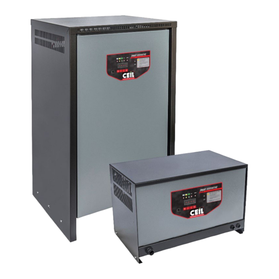
- Page 1 DERIVATIVE CHARGER with Navigator Display & Data Logging function Operation and Maintenance Manual 5DTM - 5DTT The manual refers to chargers with AT 12 board with FW 6.4L or higher (dec 2021) Slightly differences can be found using different versions...
-
Page 3: Electrical Information
rev. 1904 (EX - FW 6.4) WARNING - SAFETY FOR LEAD-ACID BATTERY AND ASSOCIATED BATTERY CHARGER SYSTEM Electrical information Read the electrical data on the charger identification plate and ensure they match your electric system and the battery it should recharge: Mains AC voltage. -
Page 4: Installation And Powering
rev. 1904 (EX - FW 6.4) Safety and Reference Rules The Battery Charger is made in accordance with the following ECC rules: 2014/35/UE Rules for low voltage equipment 2014/30/UE Electromagnetic compatibility and products norms EN60335-1 and 60335-2-29. Chargers are manufactured under ISO9001 conditions Only certified electricians should arrange the connection of the Charger to AC Mains supply. -
Page 5: Visual Indications
rev. 1904 (EX - FW 6.4) Charging profile Wa - features Chargers perform a decreasing current profile called Wa with dU/dt termination regulated by the rule DIN 41774 The charge cycle is divided in two parts: The bulk phase: from beginning of the charge up to the gassing point (2.4Vel) The final charger: from gassing point (2.4Vel) up to the end of the charge. -
Page 6: Navigator Display
AC phase (1) Alarm (2) Firmware (34) eg: 5DTT 5DTM The last 3 codes (11-12-13) are "setting identity codes". Necessary in case of fault or PCB replacement. Numbers reported between brackets represents the digit of the display: 1 = digit 1. 2 = digit 2 etc (#) From FW rev 6.6 on code 1 has been divided in two (Code_1A - Vbat - 48... - Page 7 1 - 5DTM is a single phase charger, while 5DTT is three phase 2 - 5DTM does not have an auxiliary transformer that powers the main board and the display, therefore it is not possible to obtain information without connecting the battery.
-
Page 8: Operation
Charger Power-up and Battery Recharge Charger performs the cycle automatically just after its connection to the battery and to AC Mains. WARNING: The single phase 5DTM and the three phase 5DTT are slightly different during their starting up This is the procedure to follow:... - Page 9 rev. 1904 (EX - FW 6.4) TROUBLE SHOOTING - Three Phase - 5DTT This information relates to a 5DTT charger with a DC current reader andwith an auxiliary transformer (P4=3) Legend: -- = LED is off On = LED is ON steady L = LED is flashing Situations BEFORE the charge (1-9) and DURING the charge (10-20)
- Page 10 4) Wrong card setting 5) Diode bridge failure STAND-BY MODE: The 5DTM chargers do not have AC auxiliary power but only battery power. To preserve energy, the display switches to standby mode after a minute. For 1 sec shows the last data and for 4 sec it turns off ( Pressing any key it turns on for a minute.
-
Page 11: Preliminary Recommendations
rev. 1904 (EX - FW 6.4) 6. MAINTENANCE The maintenance schedule depends on use and operating conditions but. generally. it should not exceed three months. The maintenance operations have to be made by specialised personnel. in compliance with safety rules. “Routine and Extraordinary Maintenance Forms”... - Page 12 rev. 1904 (EX - FW 6.4) 8. INPUT AC CURRENT DRAW AND FUSE RATINGS 1 phase 240V 3 phase 420V Mains Cur. Fuse Mains Cur. Fuse 12,7 15,8 19,0 22,2 25,3 10,3 11,9 14,3 19,0 23,8 28,5 33,3 38,0 11,2 12,6 10,2 14,0...
- Page 13 rev. 1904 (EX - FW 6.4) 13 /20...
-
Page 14: Installation Form
rev. 1904 (EX - FW 6.4) 9- Installation Form The purpose of this form is to: Verify the compatibility among Charger. Battery and AC Mains. Following these instructions will lead to verify the points that have the higher probability of fault. This document will help confirm that the installation was carried out properly. - Page 15 rev. 1904 (EX - FW 6.4) 10- Routine Maintenance Form The purpose of this form is to: Verify the general condition of the charger. Following these instructions will lead to verify the points that have the higher probability of fault. This document will help confirm that periodical inspection has been conducted.
- Page 16 rev. 1904 (EX - FW 6.4) 11- Extraordinary Maintenance Form The purpose of this form is to: Verify the general condition of the charger. Prevent / rectify faults. Following these instructions will lead to verify the points that have the higher probability of fault. This document will help confirm that periodical inspection has been conducted.
- Page 17 rev. 1904 (EX - FW 6.4) 12. Charger Selection Table Battery Ah Rechargred in Model 8 - 9 hours 12 - 13 hours Starting Current From 80% discharged state Amps (Ah at 5 hour rate) 1,120 1,280 1,440 1,100 1,600 Note: Data relates to DoD 80% and CF 17% margin +/- 1/2 h (4,7%) 17 /20...
- Page 18 rev. 1904 (EX - FW 6.4) NOTES ____________________________________________ ____________________________________________ ____________________________________________ ____________________________________________ ____________________________________________ ____________________________________________ ____________________________________________ ____________________________________________ ____________________________________________ ____________________________________________ ____________________________________________ ____________________________________________ ____________________________________________ ____________________________________________ ____________________________________________ ____________________________________________ ____________________________________________ ____________________________________________ ____________________________________________ ____________________________________________ ____________________________________________ ____________________________________________ ____________________________________________ 18 /20...
Need help?
Do you have a question about the 5DTM and is the answer not in the manual?
Questions and answers