Table of Contents
Advertisement
Quick Links
Advertisement
Table of Contents

Summary of Contents for Indigo Carlson RuralConnect Gen3
- Page 1 ® RuralConnect Gen3 TV White Space Radio User Manual V1.0...
- Page 2 Local product support is provided by Indigo Broadband in South Africa. The first point of contact should always be via their support facilities which is available from 8:00 AM to 5:00 PM CAT, excluding weekends and public holidays.
- Page 3 Proper Handling and Grounding ® The electronic components of the RuralConnect equipment are sensitive to electrostatic discharge (ESD). In order to prevent potential warranty voiding damage, you must use an adequately grounded anti-static wrist strap when handling the equipment. It is also important to avoid the use of conductive tools.
- Page 4 When the system is operational, avoid standing directly in front of the antenna. Strong RF fields are present when the transmitter is on. The antenna must not be deployed in a location where it is possible for people to stand or walk inadvertently in front of the antenna. Regulatory Compliance Information Warning: Changes or modifications to this device not expressly approved by Carlson Wireless Technologies Inc.
-
Page 5: Table Of Contents
Table of Contents Introduction ........................10 Scope of Manual ......................10 Product Overview......................10 System Planning ........................12 Proper Handling ......................12 Grounding ........................12 Lightning Protection ....................12 Cable Recommendations ....................13 Recommended Tools ....................13 Computer Required .....................14 Spectrum Management ....................14 2.7.1. Unlicensed Operation using a White Space Database .........14 2.7.2. - Page 6 Home Page .........................40 LAN Configuration.......................40 5.2.1. DHCP Server .......................41 Traffic Shaping ......................42 TVWS Status ......................43 Field-Testing and Installation .....................44 Professional Installers ....................44 Antenna Height and RF Exposure Warnings ...............44 Outdoor Unit (ODU) ....................44 6.3.1. Mounting the ODU ....................44 ® RuralConnect Antennas ....................45 6.4.1.
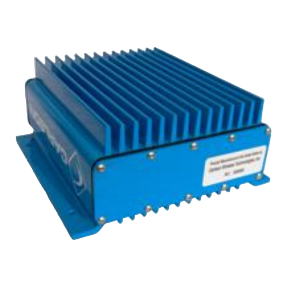
- Page 7 Figures ® Figure 1: RuralConnect Outdoor Unit ..................10 Figure 2: Security warning while attempting to access the GUI ..........19 Figure 3: GUI Login ........................19 Figure 4: System Status ......................19 Figure 5: Setting up new CPE ....................19 Figure 6: Manager Screen ......................20 Figure 7: Location Screen ......................20 Figure 8: Location Override Screen ...................20 Figure 9: Setting Manual Location Details .................20...
- Page 8 Figure 47: Step 3. Covering Rubber Tape with Electrical Tape ..........47 Figure 48: Base Station RF Surge Protector Diagrams .............50 Figure 49: CPE RF Surge Suppressor ..................51 Figure 50: POE Surge Protector ....................51 RuralConnect® Gen3 User Manual V1.0 Page | 8 of 57 ©...
- Page 9 Tables Table 1: Sector Antenna Specifications ..................45 Table 2: Log Periodic Directional Antenna Specifications ............46 Table 3: High-Value Base Station RF Surge Protector Specifications ........50 Table 4: CPE RF Surge Protector Specifications ..............51 Table 5: 640-6550 POE Surge Protector Specifications ............51 RuralConnect®...
-
Page 10: Introduction
1. Introduction Scope of Manual The purpose of this manual is to provide professional planning and installation personnel with the appropriate information and procedures required to install and operate the RuralConnect TV White Space Broadband Radio and accessory equipment. In order to avoid harm to persons or damage to the product, please ensure that you have read and understand the safety, unpacking, and installation sections before proceeding. - Page 11 ® In Africa, the RuralConnect is only available with an 8 MHz channel bandwidth. The system is fully compliant with ETSI EN 301-598 regulations. To prevent exceeding an authorized power limit the radio includes an internal RF sensor that reads the RF power output.
-
Page 12: System Planning
2. System Planning Proper Handling ® You must follow precautionary measures when handling RuralConnect devices. Improper handling of your equipment may cause damage and void your warranty. The electronic components of the ® RuralConnect equipment are sensitive to electrostatic discharge (ESD). Whenever handling the equipment, always use adequate ESD protection, such as a grounded anti-static wrist strap. -
Page 13: Cable Recommendations
protection for your equipment. Verified ground connections are imperative for lightning protection to work correctly. Primary lightning protection is located outside the enclosure. Install primary lightning protection with a good ground on all RF and/or data connections that have even a moderate outdoor line build-out. Best practices dictate all lines entering or exiting a building need protection. -
Page 14: Computer Required
Via software, unit registration requires both the owner and operator’s contact information and geo-location information. After configuration of your system, if you see any error messages or cannot obtain channel allocations, contact Indigo Technical Support. 2.7.2. Licensed/Fixed-Channel Operation... -
Page 15: Carlson Knowledge Base
Carlson Knowledge Base ® Prior to unpacking your RuralConnect equipment, we recommend reviewing the latest documentation available on our Knowledge Base. The online Carlson Knowledge Base contains a variety of useful articles that will help you get started ® with your new RuralConnect system. -
Page 16: Receiving And Testing - Quick Start Guide
3. Receiving and Testing - Quick Start Guide This section outlines the needed steps to set up the software and conduct an initial bench test before entering the field. Prior to starting these steps, you will need the following: • ®... -
Page 17: Owner & Operator Information
Geolocation Details (Latitude/Longitude) You must have each unit’s geolocation in decimal degrees. For radios not deployed, enter the coordinates for their storage location. NOTE: ETSI regulations mandate these values be accurate within 30 meters. International regulations may vary. Antenna Height WSDB registrations for each site include the antenna height above ground level (HAGL) in meters. - Page 18 search for the Base Station. For example, “Angry IP Scanner” is a free and open-source program that will ping any range of IP addresses to determine which, if any, are active. Visit http://angryip.org to learn more. The Client Station, or “CPE”, has a DHCP server running by default. If the attached computer is configured to obtain an IP address via DHCP, it will automatically obtain an IP address from the CPE.
-
Page 19: Log Into The Gui
3.4.2. Log into the GUI Open a web browser and type the URL, starting with “https://” followed by the IP address or hostname. You may be prompted with a security warning. Depending on your browser, you may need to choose an option to continue or ignore the error. -
Page 20: Figure 6: Manager Screen
Manager Figure 6: Manager Screen You should see a check in the “Enabled” box. The status must show “Channels allocated” to allow the radio(s) to transmit. Location GPS-enabled units should show the number of GPS satellites visible from the Base Station. Figure 7: Location Screen Location &... -
Page 21: Figure 10: Paws Screen
PAWS ® For compliance in regions with spectrum-sharing regulations, the RuralConnect supports the IETF Protocol to Access White Space (PAWS). PAWS is a standard used by the Base Station to connect with a White Space Database (WSDB) and get a list of available channels based on the geolocation of each radio in its network. -
Page 22: Test Internet Connection
Once the PAWS and wireless configuration details are complete, the Base Station should acquire channels from the WSDB and begin transmitting. You should see a value next to “Center Frequency (MHz)”. Browse to the Home page to view the status of each sector and any connected CPEs. Test Internet Connection Open a web browser and navigate to a webpage of your choice. -
Page 23: Base Station Graphical User Interface (Gui)
4. Base Station Graphical User Interface (GUI) The following section provides an overview of the web-based Graphical User Interface (GUI) that operates within your Local Area Network (LAN). When used with a limited number of Base Stations, the GUI provides a cost effective and simple way to manage the units both in the field and remotely. We recommend you familiarize yourself with the GUI on the bench prior to outdoor testing and deployment. -
Page 24: Figure 14: Base Station User Interface - Radio Manager Flowchart
Set up Radios Make sure the Unless you want antenna height shared access, make the SSID’s above ground level is correct. different per sector Go down To Radio Manager Screen Check the Note that, like Wifi, “manager status” your encryption does it say “... -
Page 25: Figure 15: Base Station User Interface - Cpe Management Flowchart
Set up CPE’s Go to the CPE Management screen If you have aThe system will recognize Add New CPE’s and enter details such as DHCP or set IP address for each one desired. After connecting the system together using the test bench attenuator set, your CPE’s should... -
Page 26: Connecting To The Base Station
Connecting to the Base Station To begin the login process, start by plugging the base unit into your Ethernet network. You will use a web browser to connect to the web-based Graphical User Interface, or “GUI”. From a computer on your LAN, open a web browser and browse to “http://{ip address}”. If you do not know the IP address, or for more information, see Section 3.4.1: Finding the Base Station. -
Page 27: Figure 17: Base Station User Interface - User Accounts Screen
Figure 17: Base Station User Interface - User Accounts Screen New accounts may be created by pressing the “New User” button. This adds a line to the account list. Usernames may be changed by clicking on them and typing a new name, as shown in the figure. -
Page 28: Radio Manager
4.2.2. Radio Manager The Radio Manager top-level page allows the installation and commissioning of the base station. Figure 18: Base Station User Interface - Radio Manager Screen This page is divided into sections. At the top is the regulatory authority for which the base station is constructed. -
Page 29: Contact Details
The third block shows a summary of the Location information. The antenna height above the ground should be entered here; the height is used when communicating with the PAWS database. More information regarding the state of the GPS module is available by clicking the “GPS Details”... -
Page 30: Cpe Management
Figure 20: Base Station User Interface - GPS Screen CPE Management This is one of the most important Screens on the user interface. It shows details of the CPEs that are connected to the base station and allows their configuration, both before and after they connect. Figure 21: Base Station User Interface - CPE Management The CPE Management page consists of a list of CPE that are connected and/or configured. -
Page 31: Edit Cpe Configuration
Enter the MAC address of the CPE (it is the MAC address that is used to globally identify CPE) along with other appropriate configuration. A CPE can also be provisioned once it is connected. A CPE that is connected to the base station that does not have provisioning information will appear in the list without the configuration columns. -
Page 32: Ethernet Port
NAT Router The most common operating mode of a CPE for IP version 4. This mode behaves in the same way as many domestic DSL routers. The CPE separates the network in the uplink direction (through the radio) from the network in the customer premises. -
Page 33: Bridge Routing Table
Figure 23: Base Station User Interface - Ethernet Port Setup Screen In addition to the Port Configuration function, there are buttons at the bottom of the page that provide access to other Ethernet related Screens. 4.4.1. Bridge Routing Table The base station contains a learning bridge that is used to route traffic between the Ethernet port and the radios. -
Page 34: Vlan Details
Figure 24: Base Station User Interface - Ethernet Port Bridge Routing 4.4.2. VLAN Details The base station has basic support for 802.1q VLAN tagging. This sub-page allows the VLAN configuration of the Ethernet and radio ports to be specified. In addition, packet counts on each port are shown, which is sometimes useful for diagnosing issues. -
Page 35: Interface Status
Figure 25: Base Station User Interface - Ethernet Port VLAN Settings 4.4.3. Interface status The Interface Status sub-page indicates the connection state and speed of the Ethernet connection. RuralConnect® Gen3 User Manual V1.0 Page | 35 of 57 © Copyright 2020 Carlson Wireless Technologies, Inc. -
Page 36: Traffic Shaping
Figure 26: User Interface Ethernet Interface Status Traffic Shaping The base station and CPE together provide a traffic shaping scheme that allows individual CPE (and in router and bridge modes, individual devices behind the CPE) to be assigned maximum and committed information rates (MIR and CIR) in both the downlink and uplink directions. -
Page 37: Figure 29: Base Station User Interface - Ul/Dl Traffic Shaping Device List
Figure 29: Base Station User Interface - UL/DL Traffic Shaping Device List The second step is to assign classes to CPE devices. This is done through the CPE Management page. Go there, select the desired CPE and click the “Traffic Shaping” button. Clicking “New Device”... -
Page 38: Snmp
SNMP The base station supports element management systems that communicate using SNMP version 1 or 2. This page allow configuration according to your SNMP management plan. Figure 32: Base Station User Interface - SNMP Setup Screen Application Software The Application Software page reports the current version of software running on the unit. The base station can store two versions of the application, one of which is currently running. -
Page 39: Key Parameters
Key Parameters The base station collects statistical information from various sources while running. This information is available for view and download on the Key Parameters page. Users can choose what information is displayed on the live graph by placing tick marks against their desired items. -
Page 40: Cpe User Management Interface
5. CPE User Management Interface The CPE provides a similar set of web pages as the base station to allow local monitoring and configuration. Setting a CPE up and connecting a browser to it is a little different. The factory default state for the CPE Ethernet port is a fixed IP address of 192.168.2.1 and subnet mask of 255.255.0.0. -
Page 41: Dhcp Server
Figure 37: CPE User Interface – LAN Configuration Screen LAN Configuration Buttons - CPE The page also has buttons for the Routing Table (see 4.4.1), Interface Status (see 4.4.3) and VLAN Details (see 4.4.2); all identical in operation to the base station. Finally, there is a button for the DHCP Server. -
Page 42: Traffic Shaping
Figure 39: CPE User Interface – DHCP Server Screen Traffic Shaping The traffic shaping system is controlled by the base station, as described in section 4.5. The traffic shaping page on the CPE shows the devices that the CPE will shape the traffic for in the uplink for diagnostic purposes. -
Page 43: Tvws Status
TVWS Status The CPE radio’s status is monitored through the TVWS Status page. The few items of radio configuration are also on this page. The main ones are the SSID and Passphrase, which must match the base station configuration. Part of the acquisition sequence the CPE goes through is a survey of available channels. -
Page 44: Field-Testing And Installation
RuralConnect Gen3 radio uses external antennas that operate over the entire UHF band (470 MHz to 790 MHz). Speak to your Indigo Sales Representative about the antenna selection available. Clients connect to a Base Station via a UHF radio signal. Due to the... -
Page 45: Ruralconnect Antennas
® RuralConnect Antennas ® The following ETSI - authorized antennas are available for use with the RuralConnect in the United States. Currently, no other manufacturer produces antennas authorized for use with the ® RuralConnect . For 360-degree coverage, you will use three (3) 120-degree Carlson Sector Antennas (model # 053-470-786-75-8), each connected to one of the three Base Station radios. -
Page 46: Figure 44: Log Periodic Direction Antenna Radiation Pattern And Gain Chart
Model Number 057-470-862-10.5-F Antenna Type Log Periodic Polarity Vertical or Horizontal Front-to-back-ratio 36 dB Return Loss -15 dB Beamwidth (-3 dB) +/- 28 degrees Maximum Mast Diameter 60 mm “F” type female 75 Ohms Antenna Connector Frequency Range 470-862 MHz Gain 10 - 11 dBi 1kg –... -
Page 47: Weatherproofing Rf Connections
Weatherproofing RF Connections Once you have mounted and secured your antenna, we recommend completing the installation by properly weatherproofing the RF connector. The connector must be waterproof, durable, and easy to remove/service. You will need: • Vinyl/electrical tape • Rubber (butyl) tape, a thick, sticky sealing tape, commonly known as “vapor wrap.” We recommend 3M 3339 tape. -
Page 48: Antenna Alignment
Antenna Alignment Omni-Directional Base Station Antenna While Omni-directional antennas do not require alignment, you must consider placement concerns. Avoid mounting adjacent to a metal object when possible. When mounting to the side of a tower, always use a standoff of one meter or more. Place the mount toward the top of the standoff pole. For cabling, always mount securely near the antenna and use a small jumper coax cable to avoid tension on the antenna connections. -
Page 49: Interference Solutions
LEDs) will be different between these points. The web interface can help you determine if the antenna needs to be realigned for an improved uplink. Interference Solutions Interference problems can arise with external devices installed near the antenna or radio, including external devices later installed. -
Page 50: Figure 48: Base Station Rf Surge Protector Diagrams
To protect against these current surges, Installer must use a coaxial lightning protector in the antenna line as primary protection. The RF Lightning Suppressor is often installed near the RF antenna port and/or the grounded antenna entry point of the building (or outdoor cabinet). -
Page 51: Power-Over-Ethernet Surge Protection
CPE RF Surge Protector Carlson Part Number 640-6565 Frequency Range 5-1000 MHz Insertion Loss <1 dB Return Loss >18 dB DC Breakdown Voltage 120 min, 297 max Surge Current (10 Operations 8/20µS) 10 kA Capacitance 2 pF max Impedance Match 75 Ohms Figure 49: CPE RF Surge Table 4: CPE RF Surge Protector Specifications... -
Page 52: Appendices
7. Appendices Specifications 7.1.1. System Frequency Bands UHF 470-790 MHz (US and ETSI) Channel Spacing 6 MHz (US), 8 MHz (ETSI) Modulation BPSK, QPSK, 16QAM, 64QAM, 256QAM RF Data Rates 1.8 up to 32 Mb/s RF Data Rate Control Dynamic or Fixed RF Receive Interface Proprietary technology is used to reduce co-channel interference... -
Page 53: Mechanical
7.1.7. Mechanical Dimensions 19cm x 8,25cm x 22,8cm Enclosure Material Painted steel Weight 2,5kg 25mm – 50mm vertical mast Mounting 7.1.8. Power Supply Input Voltage 100-240 VAC, 50 - 60 Hz Output Voltage 48 VDC (CPE), 56 VDC (Base Station) Current Draw - Base Station Tx: 25W, Rx: 9W, Idle: 7W Current Draw - Client Station... -
Page 54: Acronyms/Abbreviations
Acronyms/Abbreviations 16QAM Quadrature Amplitude Modulation (16-states) 256QAM Quadrature Amplitude Modulation (256-states) 64QAM Quadrature Amplitude Modulation (64-states) Application Programming Interface BPSK Binary Phase-Shift Keying Base Station Customer Premises Equipment (Client Station) Decibel Downlink Electromagnetic Compatibility Electrostatic Discharge FTDI Future Technology Devices International GNSS Global Navigation Satellite System (GPS, GLONASS, Galileo, BeiDou) Graphical User Interface... -
Page 55: Glossary
Glossary Access Point A device that allows a wireless device (or multiple devices) to connect to a network (or the Internet) Attenuation Amplitude reduction of an electrical signal Bits per second, the rate of at which data is transmitted Byte A digital “word”... -
Page 56: Useful Urls
Orthogonal Frequency Division Multiplexing (OFDM) A digital multi-carrier modulation method used with Fast Fourier Transform algorithms to achieve very high throughput and increase spectral efficiency Special Temporary Authority (STA) A temporary broadcast license that allows a broadcast station to operate outside of its normal technical or legal parameters Useful URLs Carlson provides the following URLs for reference purposes only. - Page 57 Tower Safety Information Tower installation crews MUST be adequately trained, licensed, and properly equipped with all of the safety equipment required by law. Failure to follow federal and/or local regulations may result in warranty voiding equipment damage, personal injury, fines, and/or the loss of applicable licenses. Information provided here is strictly for reference purposes.