Advertisement
Revison
Change
1
Initial release
2
Use of Maxon motor
S
UPPLEMENTARY
SI-001 PC M
Part / Assy #
Drawing #
Applicability
Compliance
SUBJECT:
1.
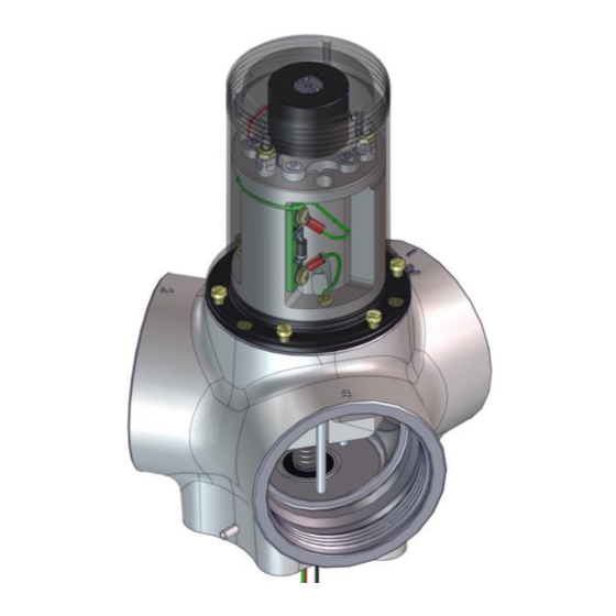
These instructions cover the replacement of the Globe pitch change motor assembly (A0326-180 or
A0326-320) with the Maxon pitch change assembly A0455-150 or A0455-231 in all AH-xxx hub
assemblies.
These instructions should be carefully followed during the motor replacement procedure.
Caution:
This assembly procedure should only be carried out by persons authorised by
Airmaster Propellers Ltd to conduct blade set-up.
Z:\3 Production\3.3 Product Documentation\3.3.6 Supplementary Instructions\SI-0001 PC Motor Replacement AP332F\SI-001-R2 PC Motor Replacement Maxon.Docx, created on 16/2/16 by Martin,
OTOR
M
A0455-x
All AH-x hubs currently using Globe PC motor
REPLACE PC MOTOR IN AP-X HUB ASSEMBLY
Introduction
Approved
Date
mje
12/06/14
mje
16/02/16
I
NSTRUCTION
R
EPLACEMENT
AXON
Airmaster Propellers Ltd
Ph:
20 Haszard Rd,
Massey
Fax:
PO Box 374,
Kumeu
Email:sales@propellor.com
Auckland,
New Zealand
Web:
www.propellor.com
last saved on 11/5/16, printed on 11/5/16.
+64 9 833 1794
+64 9 833 1796
Advertisement
Table of Contents

Summary of Contents for airmaster SI-001
- Page 1 This assembly procedure should only be carried out by persons authorised by Airmaster Propellers Ltd to conduct blade set-up. Z:\3 Production\3.3 Product Documentation\3.3.6 Supplementary Instructions\SI-0001 PC Motor Replacement AP332F\SI-001-R2 PC Motor Replacement Maxon.Docx, created on 16/2/16 by Martin, last saved on 11/5/16, printed on 11/5/16.
- Page 2 SI-001-r2 SI-0001 PC Motor Replacement AP332F (Maxon) Page 2 Material Information Parts Required Item Assy No. Description A0455-150 Pitch Change Gearmotor Assy Maxon (High Speed) A0455-231 Pitch Change Gearmotor Assy Maxon (Std Speed) Tooling Item Part Number Description Phillips Screwdriver (PH2) Flat Blade Screwdriver (1.2 x 6.5mm)
- Page 3 SI-001-r2 SI-0001 PC Motor Replacement AP332F (Maxon) Page 3 Procedure Preparation Select a suitable space to perform this maintenance. Space should be clean, dry and well lit. Suitable containers should be available for separation and identification of parts and fasteners.
- Page 4 SI-001-r2 SI-0001 PC Motor Replacement AP332F (Maxon) Page 4 Remove screws to motor wires, prop wires Roll the red and black motor cables into and link wire. the grooves on top of the pitch change motor cap and secure with thin tape.
- Page 5 SI-001-r2 SI-0001 PC Motor Replacement AP332F (Maxon) Page 5 Assembly Carefully insert the Maxon pitch change motor into the hub assembly ensuring that the pins in the motor coupling engage properly with the shaft coupling. If the pins do not align with the spindle Attach the pitch change motor.
- Page 6 PCB mounted microswitches. Ask Airmaster for guidance. Place the PC Brake Cover onto the motor. Attach PC Motor Clamp to microswitch Ensure that the wires align with the slot.
- Page 7 SI-001-r2 SI-0001 PC Motor Replacement AP332F (Maxon) Page 7 Connect the three prop power wires (Feather - black, red, green) to microswitch mount assembly. Fit and connect feather link wire to micro-switch mount assembly. Connect motor wires.
- Page 8 SI-001-r2 SI-0001 PC Motor Replacement AP332F (Maxon) Page 8 Secure PC motor lead wires with heat shrink to keep motor wires clear of pitch change limit rods. Fit the motor cap Test hub assembly for correct operation...
Need help?
Do you have a question about the SI-001 and is the answer not in the manual?
Questions and answers