
Summary of Contents for ISCO 750
- Page 1 750 Area Velocity Module Installation and Operation Guide Part #60-9003-465 Copyright © 1996. All rights reserved, Isco, Inc. Revision E, January, 2003...
- Page 3 Isco recommends that you read this manual completely before placing the equipment in service. Although Isco designs reliability into all equipment, there is always the possibility of a malfunction. This manual may help in diagnosing and repairing the malfunction.
- Page 5 être affaiblie; cela augmentera votre risque de blessure. WARNING If this system uses flammable organic solvents, Isco recommends that you place this system in a well-ventilated environment, designed for these types of materials. This environment should be constructed in accordance with federal, state, and local regulations.
- Page 6 Ce système peut utiliser des dissolvants organiques inflammables. Pour réduire le péril qui peut être causé par l'accumulation des vapeurs explosives, Isco recommande que vous installez ce système dans un environnement bien-aéré qui est conçu pour les matières hasardeuses. Cet environnement devrait être construit selon les règlements...
-
Page 7: Table Of Contents
List of Figures 2-1 6712 Programming: 750 Module Screens ....... . 2-3 2-2 6712 Programming: 750 Module Setup Screens . - Page 8 List of Tables 1-1 Technical Specifications for the 750 Area Velocity Module ....1-2 1-2 Technical Specifications for the Standard AV Sensor ..... . 1-2 1-3 Technical Specifications for the Low Profile AV Sensor .
-
Page 9: Section 1 Introduction
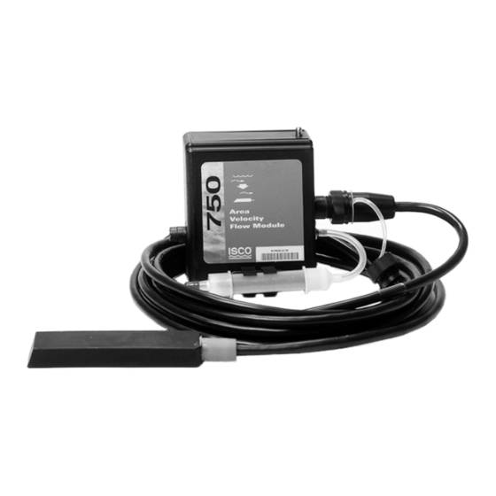
750 Area Velocity Module Section 1 Introduction 1.1 Overview The Model 750 Area Velocity Module is one of Isco’s inter- changeable modules for the 6700 Series Samplers. The module enhances sampler operation by providing flow-pacing and addi- tional sampler enable conditions. The sampler also displays the real-time level, velocity, flow rate, and total flow provided by the module. -
Page 10: Technical Specifications
General notes: • All weights may vary by ± 0.2 lb (0.1 kg). • All lengths may vary by ± 0.25 inches (0.64 cm) Table 1-1 Technical Specifications for the 750 Area Velocity Module Weight 0.9 lbs (.4 kg) 4.9 × 5.7 × 2.0 inches (12.4 × 14.5 × 5.1 cm) -
Page 11: Technical Specifications For The Low Profile Av Sensor
750 Area Velocity Module Section 1 Introduction Table 1-2 Technical Specifications for the Standard AV Sensor (Continued) Maximum Allowable level Standard Range 20 ft (6.1 m) Extended Range 40 ft (12.2 m) Level Measurement Accuracy Standard Range 0.033 to 5.0 ft: ± 0.008 ft/ft (0.01 to 1.52 m: ± 0.008 m/m) >5.0 ft: ±... -
Page 12: Power Sources
1.3 Power Sources We recommend using a Lead-Acid battery or a new 913 or 923 power pack when using the Model 750 Area Velocity Module. A nickel-cadmium battery may not be sufficient to finish a sample routine. For example, a nickel-cadmium battery should be... -
Page 13: Velocity Measurement
750 Area Velocity Module Section 1 Introduction The difference between the pressures exerted on the diaphragm is the hydrostatic pressure. The transducer converts the hydro- static pressure to analog signals. The signals are sent to the module. Because pressure is proportional to the level of the stream, the module can convert the analog signal to a level measurement. - Page 14 750 Area Velocity Module Section 1 Introduction...
-
Page 15: Section 2 Installation And Programming Basics
750 Area Velocity Module Section 2 Installation and Programming Basics The 750 can be used in a wide range of applications. In the “Flow Meter” mode of operation, the module will produce sound results if you properly choose an installation site, select an appropriate flow conversion method, and program the module with accurate measurements. -
Page 16: Programmed Enable
2.3 Selecting a Site The 750 is designed to measure flow in open channels without a primary device. A primary device is a hydraulic structure, such as a weir or a flume, that modifies a channel so there is a known relationship between the liquid level and the flow rate. - Page 17 . Continue with sampler programming. See sampler manual. Figure 2-1 6712 Programming: 750 Module Screens...
- Page 18 L e v e l t o f l o w r a t e s h o w n . P L E A S E W A I T ! . . . S O R T I N G D A T A Figure 2-2 6712 Programming: 750 Module Setup Screens...
- Page 19 I N T E R V A L I N M I N U T E S : S T O R A G E I N T E R V A L Continue with sampler programming. See sampler manual. Figure 2-3 6712 Programming: 750 Module Quick View Screens...
-
Page 20: Selecting A Flow Conversion Method
750 Area Velocity Module Section 2 Installation and Programming Basics 2.4 Selecting a Flow The 750 is capable of determining flow rates using either area velocity conversion or level-to-flow rate conversion. A list of Conversion Method available flow conversions appears in Table 2-1, Flow Conversion Methods. -
Page 21: Flow Conversion With A Primary Device
Manning formula. To use the Manning formula you must be able to provide the channel slope, a roughness coefficient, and a channel diameter or width. For more information on the Manning formula, refer to the Isco Open Channel Flow Mea- surement Handbook. 2.5 Measurements for At a minimum, module programming requires a level mea- surement and a zero level offset. -
Page 22: Levels And Channel Dimensions
750 Area Velocity Module Section 2 Installation and Programming Basics 2.6 Levels and Channel Channel dimensions and level measurements can vary at dif- ferent points along the channel. It is important to use measure- Dimensions ments from the same point that the AV sensor reads the velocity and level. -
Page 23: Offsets
750 Area Velocity Module Section 2 Installation and Programming Basics In round pipes it is possible to measure the level without dis- turbing the stream surface. This method is preferred. Refer to the diagram in the margin. First measure the inside diameter of the pipe (D). -
Page 24: Minimum Depth For Velocity Measurements
6712 does not have a menu selection for Minimum Depth. Instead, the Minimum Depth is automatically set to 1 inch. Probe Identification – When a probe is first connected, the 750 module will not know whether it is a Standard or Low-Profile Low Profile until it takes a velocity reading. -
Page 25: Installation Considerations
• Clean the mounting hardware between installations. CAUTION Tests have shown that the 750 Module is affected by RF radia- tion such as that from radio and TV station towers that are located nearby. If sporadic changes in water level occur as indicated on the sampler’s display, the instrument will have to... - Page 26 750 Area Velocity Module Section 2 Installation and Programming Basics below 1 inch are not a good application for the 750 and sensor. • Velocity measurements depend on the presence of some particles in the stream; either air bubbles or suspended solids.
-
Page 27: Sampler Run Time Screens
Section 2 Installation and Programming Basics 2.11 Sampler Run Time While running a sampling program, the sampler displays a variety of messages reporting the program’s status. The 750 adds Screens measurement and diagnostic information to these displays. Mea- surement information includes level, velocity, flow rate, and total BOTTLE 2 flow. - Page 28 750 Area Velocity Module Section 2 Installation and Programming Basics SAMPLER ID# 2215220899 08:55 22-FEB-03 SAMPLER ID# 2215220899 08:56 22-FEB-03 Summary Report *********** PROGRAM SETTINGS *********** ---------- AREA-VEL MODULE: 1365 SITE: FACTORY SITE DESCRIPTION: "FACTORY " Summary Report for 21-FEB-03 (FR )
-
Page 29: Section 3 Maintenance
750 Area Velocity Module Section 3 Maintenance The area velocity sensor and cable require little maintenance. Because the sensor body offers a streamlined profile to the flow, solid materials rarely collect on the sensor. However, clean the channel up- and downstream from the sensor periodically. This maintains the hydrostatic conditions on which the level-to-area conversion is based. -
Page 30: Cable Inspection
750 Area Velocity Module Section 3 Maintenance 3.1 Cable Inspection Periodically inspect the AV sensor cable and connector for wear caused by abuse or exposure to the elements. A damaged cable can affect the operation of the sensor, particularly if the reference port vent tube inside the cable is collapsed or blocked. -
Page 31: Repair Of The Module And Probe
The velocity sensor’s pressure transducer, the ultrasonic trans- ducers, cable, and the electronic components are encapsulated in plastic resin and are not user-serviceable. If you think your module or probe requires repair, contact Isco’s Customer Service Department for information on returning it to the factory. -
Page 32: Accessories
750 Area Velocity Module Section 3 Maintenance 3.6 Accessories Sensors AV Sensor 10' range (with 25' cable)... . . 60-3254-001 AV Sensor 30' range (with 50' cable)... . . 60-3254-003 Low Profile AV Sensor 10' range (with 25' cable). - Page 33 Area velocity sensor extension cable... . . 60-3254-005 Quick Disconnect Box ......60-3254-004 Isco Open Channel Flow Measurement Handbook . 60-3003-041...
- Page 34 750 Area Velocity Module Section 3 Maintenance...
- Page 35 Compliance Statements Indicating Silica Gel Material Safety Data Sheet Identity (Trade Name as Used on Label) Manufacturer MSDS Number* : MULTISORB TECHNOLOGIES, INC. (formerly Multiform Desiccants, Inc.) Address: 325 Harlem Road CAS Number* : Buffalo, NY 14224 Phone Number (For Information): Date Prepared: 716/824-8900 July 6, 2000...
- Page 36 Page 2 Section 5 - Health Hazard Data PRIMARY ROUTES Inhalation Ingestion CARCINOGEN OSHA OF ENTRY Skin Absorption Not Hazardous LISTED IN IARC Monograph Not Listed HEALTH HAZARDS Acute May cause eye, skin and mucous membrane irritation. Chronic Prolonged inhalation may cause lung damage. Signs and Symptoms Drying and irritation.
- Page 37 Isco assumes no liability for any consequential damages. * This warranty applies to USA customers. Customers in other countries should contact their Isco dealer for warranty service. In the event of instrument problems, always contact the Isco Service Department, as problems can often be diagnosed and corrected without requiring an on-site visit.
Need help?
Do you have a question about the 750 and is the answer not in the manual?
Questions and answers